


12
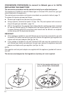
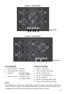
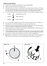
5. Check the minimum burner setting by quickly rotating the gas control knob from the
maximum to the minimum position, the ame must not go out. If adjustment is required
carry out the “minimum burner setting adjustment” procedure described below.
6. If satisfactory performance cannot be obtained, the installer shall check the installation
and notify the local gas supply authority for a gas supply problem, or if it is an ap-
pliance problem, our Customer Service Centre should be called to obtain the nearest
authorized Delonghi Service Agent.
7. Where the appliance data plate cannot be easily read with the appliance in the instal-
led position the duplicate data plate must be attached to adjacent surface and the du-
plicate Natural gas / ULPG conversion label should also be included where a Natural
gas / ULPG conversion has been completed.
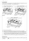
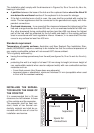
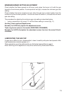
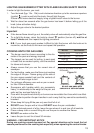
INSTALLATION WITH A FLEXIBLE HOSE ASSEMBLY
■ If this appliance has to be installed with a hose assembly, the installer shall refer to the
network operator or gas supplier for conrmation of the gas type, if in doubt.
■ When used with a exible hose, the connector on the wall should be between 800 mm
to 850 mm above the oor and in the region outside the width of the appliance to a
distance of 250 mm.
The supply connection point shall be accessible with the appliance installed.
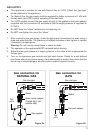
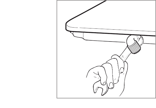
■ Flexible hose assemblies should be AS/NZS 1869 Class B or Class D certied.
The thread connection shall be Rp 1/2” (ISO 7-1) male.
■ IMPORTANT WARNING: After connection the installer must check that the hose is
not kinked, subjected to abrasion or permanently deformed. The installer must check
also that the hose is not near (or in contact) with any hot surfaces e.g. base of metal
hotplate, underbench oven etc.
■ The hose assembly shall be as short as practicable and comply with relevant
AS/NZS5601 requirements.
■ IMPORTANT WARNING: The installer shall ensure the hose assembly is restrained
from accidental contact with the ue outlet of an underbench oven.
Figure 9