


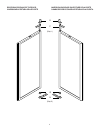
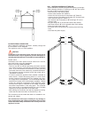
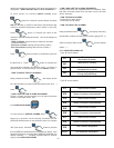
12
K
53
/
64
"
21 mm
1 37
/
64
"
4
0
m
m
53
/
64
"
21 mm
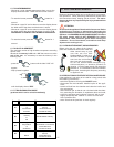
B.2.2 ELECTRICAL CONNECTION
When making the electrical connection, carefully comply with
the information on the dataplate.
The appliance works on 120V/1ph/60Hz.
CAUTION:
Connection to the electrical mains must be carried out in
accordance with current regulations and the standards re-
quired by the National Electric Code (NEC), known as NFPA 70.
Please check:
Connection to the main power must be carried out in accord-
ance with binding rules and standards.
Before connecting, make sure that:
- The line cord has an efficient grounding connection and the
main power frequency corresponds to that stated on the data
plate. If you have doubts on the efficiency of the grounding
connection have the circuit checked by a qualified technician.
- The appliance must be connected to the main power with a
permanent connection.
- In order to protect the appliance from possible overloads or
short-circuits, a fused disconnect switch or a main circuit
breaker (customer furnished) MUST be installed in the elec-
tric supply line for the appliance. It is recommended that this
switch/circuit breaker have lockout/tagout capability. Before
making any electrical connections to this appliance, check
that the power supply is adequate for the voltage, amperage,
and phase requirements on the rating plate. The customer
also must provide a grounded electrical line cord of suitable
capacity for the input specified on the data plate.
- After making the connection and with the appliance running,
check that the rated level does not fluctuate by ± 10%.
The connection must be made with cable of a suitable for am-
perage and voltage.
The manufacturer will accept no liability for any damage or
injury resulting from the violation of the above rules or of the
current electrical safety standards in the country where the
appliance is used.
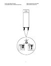
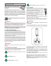
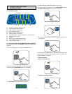
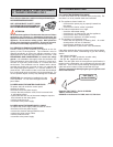
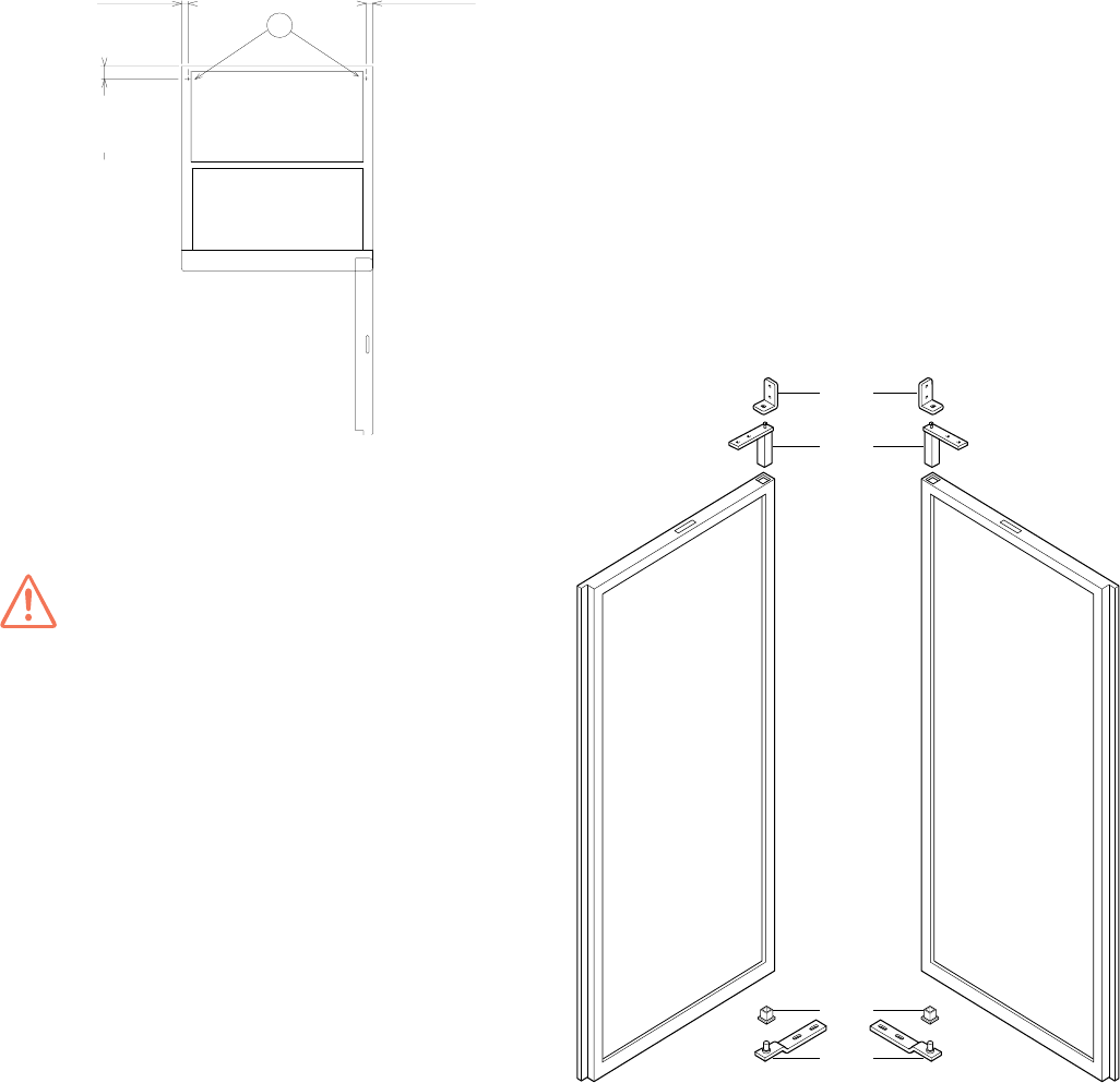
B.2.3 REVERSING OPENING OF THE DOOR
These cabinets are normally supplied with opening to the right.
When changing direction of opening so that the door opens
from left to right, proceed as follows:
• disconnect from the power supply;
• remove lower bracket “H” (Detail 2);
• remove the door and remove component “G” (Detail 2);
• unscrew the two fixing bolts from bracket “E” and the screw
which secures hinge “F” (Detail 1);
• turn the door and fit component “G” and hinge “F” on the
opposite side;
• fix upper hinge “E” on the left hand side of the cabinet;
• refit lower bracket “H” on the opposite side of the cabinet;
• fit the door onto lower hinge “H”;
• fix bracket “E” to the structure by screwing down the fixing
bolts;
• reconnect the power supply.
H
G
F
E
(Dett.1)
(Dett.2)