


26
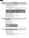
FMV156DBE
FMV156DSE
FMV156DQE
FMV156DCF
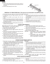
Maximum
output
70% of
maximum
output
H : GND
L : -5V
H : GND
L : -5V
ON
ON
OFF
OFF OFF
24 sec.
8 sec.
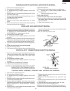
16.7 msec.
H :GND
L :-5V
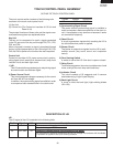
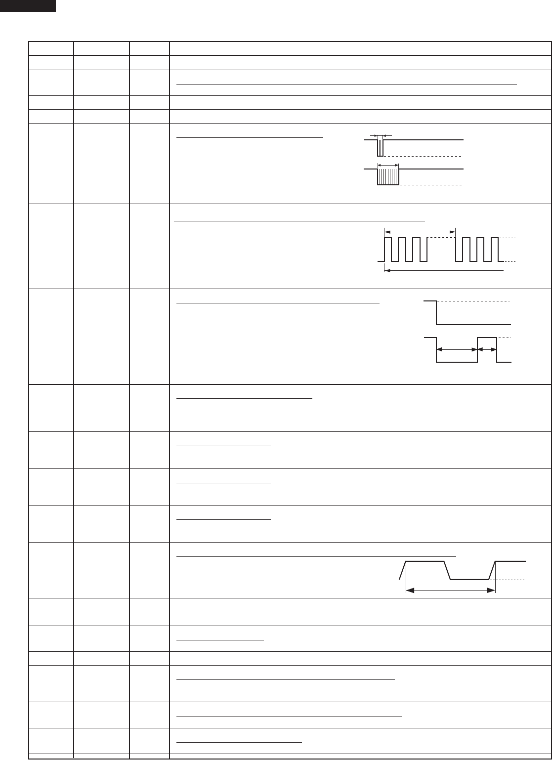
7 AN3 OUT Back light circuit (Light emitting diodes) driving signal.
8 AN2 IN
To input signal which communicates the door open/close information to LSI.
Door close "H" level signal (0V). Door open "L" level signal (-5V).
9-10 AN1-AN0 OUT Terminal not used.
11-13 P57-P55 OUT Terminal not used.
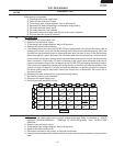
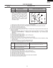
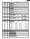
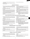
14 CNTR0 OUT
Signal to sound buzzer (2.0 kHz).
A: key touch sound.
B: Completion sound.
15 P53 OUT Terminal not used.
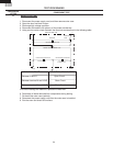
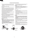
16 P52 OUT
Oven lamp, fan motor and turntable motor driving signal
To turn on and off shut off relay (RY1). The square
waveform voltage is delivered to the RY1 driving
circuit and RY2 control circuit.
17-18 P51-P50 OUT Terminal not used.
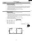
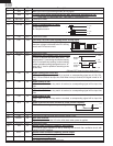
19 P47 OUT
Magnetron high-voltage circuit driving signal.
To turn on and off the cook relay (RY2). The
signals holds "L" level during microwave cooking
and "H" level while not cooking. In other cooking
modes (variable cooking) the signal turns to "H"
level and "L" level in repetition according to the
power level.
(ON and OFF times for other power level.)
20 P46 IN
Signal coming from touch key.
When either G12 line on key matrix is touched, a corresponding signal out of P20, P21,
P22, P25 and P26 will be input into P46. When no key is touched, the signal is held at "H"
level.
21 P45 IN
Signal similar to P46.
When either G11 line on key matrix is touched, a corresponding signal will be input into
P45.
22 P44 IN
Signal similar to P46.
When either G10 line on key matrix is touched, a corresponding signal will be input into
P44.
23 P43 IN
Signal similar to P46.
When either G9 line on key matrix is touched, a corresponding signal will be input into
P43.
24 INT0 IN
Signal synchronized with commercial power source frequency.
This is the basic timing for time processing of LSI.
25 P41 OUT Terminal not used.
26 P40 IN Connected to GND through the pull-down resistor R100.
27 RESET IN
Auto clear terminal.
Signal is input to reset the LSI to the initial state when power is applied.
28-29 P71-P70 OUT Terminal not used.
30 XIN IN
Internal clock oscillation frequency input setting.
The internal clock frequency is set by inserting the ceramic filter oscillation circuit with
respect to XOUT terminal.
31 XOUT OUT
Internal clock oscillation frequency control output.
Output to control oscillation input of XIN.
32 VSS IN
Power source voltage: -5.0V.
VC voltage of power source circuit input.
Pin No. Signal I/O Description
A
B
0.1 sec.
2.0 sec.
H : GND
L : -5V
H : GND
L : -5V
16.7 msec.
During cooking
H : GND
L : -5V