


33
FMV156DBE
FMV156DSE
FMV156DQE
FMV156DCF
1. Disconnect the power supply cord.
2. Open the door and block it open.
3. To discharge the high voltage capacitor, wait for 60
seconds.
4. Remove the one (1) screw holding the base cover to the
oven cavity back plate.
5. Remove the three (3) screws holding the base cover to
the oven cavity front face plate.
6. Open the base cover.
7. Release the two hood lamp sockets from the base
cover.
8. Remove the base cover from the oven cavity by pulling
down and moving to the left slightly.
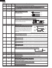
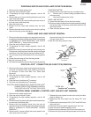
the terminal hole of the oven lamp socket with the small
flat type screw driver.
9. Now, the oven lamp socket is free.
TURNTABLE MOTOR AND FOOD LAMP SOCKETS REMOVAL
TURNTABLE MOTOR
9. Disconnect the wire leads from the turntable motor.
10. Remove one (1) screw holding turntable motor to
the oven cavity.
11. Now the turntable motor is free.
HOOD LAMP SOCKET
9. Screw the hood lamp off from the lamp socket.
10. Disconnect the wire leads from the lamp socket by pushing
the terminal hole of the lamp socket with the small flat
type screw driver.
11. Now, the lamp socket is free.
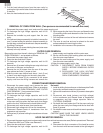
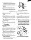
1. Disconnect the power supply cord, remove the oven from
the wall and remove the outer case. (Refer to procedure
of "REMOVAL OF OVEN FROM WALL" and "OUTER
CASE REMOVAL".). And proceed as follows.
2. Open the door and block it open.
3. To discharge the high voltage capacitor, wait for 60
seconds.
4. Remove the three (3) screws holding the hood intake duct
R to the oven cavity top plate, the oven cavity front flange
and the fan duct. And remove the hood intake duct R.
5. Turn the lamp socket and release it from the magnetron
duct.
6. Screw the oven lamp off from the lamp socket.
7. Now, the oven lamp is free.
8. Pull the wire leads from the oven lamp socket by pushing
OVEN LAMP AND LAMP SOCKET REMOVAL
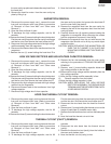
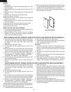
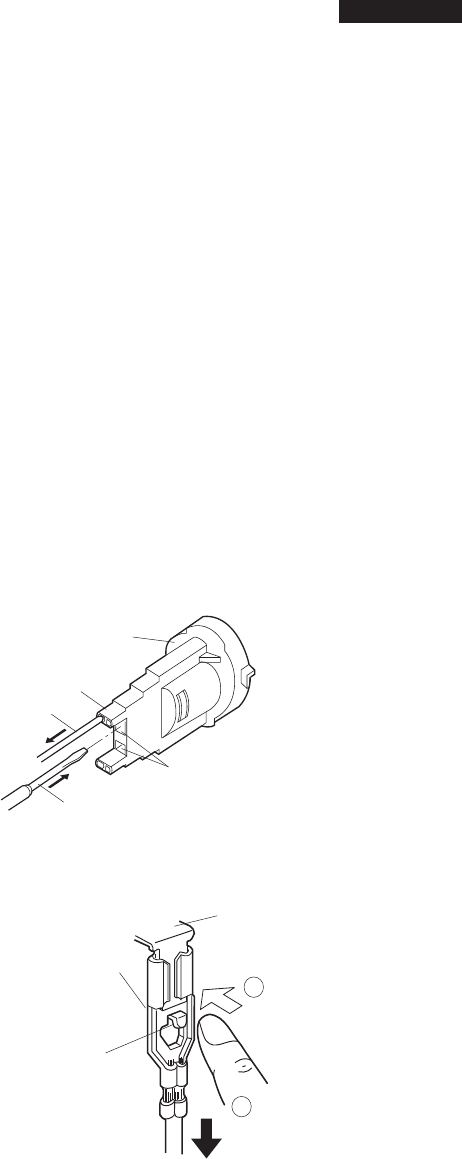
POSITIVE LOCK
®
CONNECTOR (NO-CASE TYPE) REMOVAL
1. Disconnect the power supply cord and remove the oven
from wall and remove outer case. (Refer to procedure
of "Removal of Oven from Wall" and "Outer case
Removal")
2. Open the door and block it open.
3. To discharge the high voltage capacitor, wait for 60
seconds.
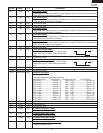
4. Push the lever of positive lock
®
connector.
5. Pull down on the positive lock
®
connector.
CAUTION: WHEN CONNECTING THE POSITIVE LOCK
®
CONNECTORS TO THE TERMINALS, INSTALL
THE POSITIVE LOCK
®
SO THAT THE LEVER
FACES YOU.
Positive lock
®
connector
Oven lamp
socket
Terminal
Wire lead
Terminal hole
Flat type small
screw driver
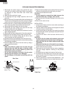
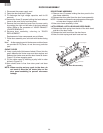
2. Open the door and block it open.
3. To discharge the high voltage capacitor, wait for 60
seconds.
4. Remove three (3) screws holding the hood exhaust louver
to oven cavity front face plate.
5. Remove the hood exhaust louver from the oven by
pushing the right and left tabs of the hood exhaust louver.
(Refer to procedure of "HOOD EXHAUST LOUVER
REMOVAL")
6. Remove one (1) screw holding the control panel to the
oven cavity front face plate.
CONTROL PANEL ASSEMBLY, CONTROL UNIT AND KEY UNIT REMOVAL
1. Disconnect the power supply cord.
7. Release the control panel from the oven cavity front face
plate by lifting it up.
8. Disconnect the wire leads from the relays RY1 and
RY2.
9. Disconnect the connectors CN-A, CN-C and CN-E from
the control unit.
10. Remove the control panel assembly from the oven.
11. Now, the control panel assembly is free.
12. Disconnect the connector CN-G from the control unit.
13. Remove two (2) screws holding the power unit to the key
Terminal
Push
Pull down
1
2
Lever
Positive lock¨
connector