


35
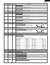
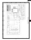
FMV156DBE
FMV156DSE
FMV156DQE
FMV156DCF
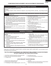
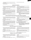
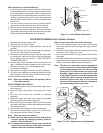
After adjustment, check the following.
1. In and out play of door remains less than 0.5mm when
in the latched position. First check upper position of latch
hook, pushing and pulling upper portion of door toward
the oven face. Then check lower portion of the latch hook,
pushing and pulling lower portion of the door toward the
oven face. Both results (play in the door) should be less
than 0.5mm.
2. The door sensing switch and primary interlock switch
interrupt the circuit before the door can be opened.
3. Monitor switch contacts close when door is opened.
4. Re-install outer case and check for microwave leakage
around door with an approved microwave survey meter.
(Refer to Microwave Measurement Procedure.)
Figure C-1. Latch Switch Adjustments
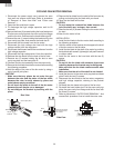
2. Open the door and block it open.
3. To discharge the high voltage capacitor, wait for 60
seconds.
4. Remove the three (3) screws holding the hood exhaust
louver to the oven cavity front face plate.
5. Remove the hood exhaust louver from the oven cavity
by pushing the right and left tabs of the hood exhaust
louver. (Refer to the procedure of "HOOD EXHAUST
LOUVER REMOVAL".)
6. Insert a putty knife (thickness of about 0.5mm) into the
gap A between the door stopper and the choke cover
as shown in Figure C-3 to free engaging parts.
7. Lift up the door stopper.
8. Now, the door stopper is free from the door assembly.
9. Lift up the door assembly to release the upper and lower
door hinge pins from the upper and lower oven hinges.
10. Now, the door assembly is free.
Note: When the individual parts are replaced, refer to
"Door Disassembly".
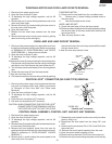
DOOR ASSEMBLY RE-INSTALL
1. On re-installing door, insert the lower oven hinge to lower
door hinge pin.
2. Insert the upper oven hinge to the upper door hinge
pin.
3. Shut the door (close the contacts of interlock
switches).
4. Make sure upper and lower oven hinges are inserted
into the upper an lower door hinge pins.
5. Make sure the door is parallel with oven face lines (left
and upper side lines) and door latch heads pass through
latch holes correctly.
6. Re-install the door stopper to the door assembly.
7. Re-install the hood exhaust louver to the oven cavity
front face plate with the three (3) screws.
Note: After any service to the door;
(A) Make sure that door sensing switch and primary
interlock switch are operating properly. (Refer to
chapter "Test Procedures".)
(B) An approved microwave survey meter should be
used to assure compliance with proper microwave
radiation emission limitation standards.
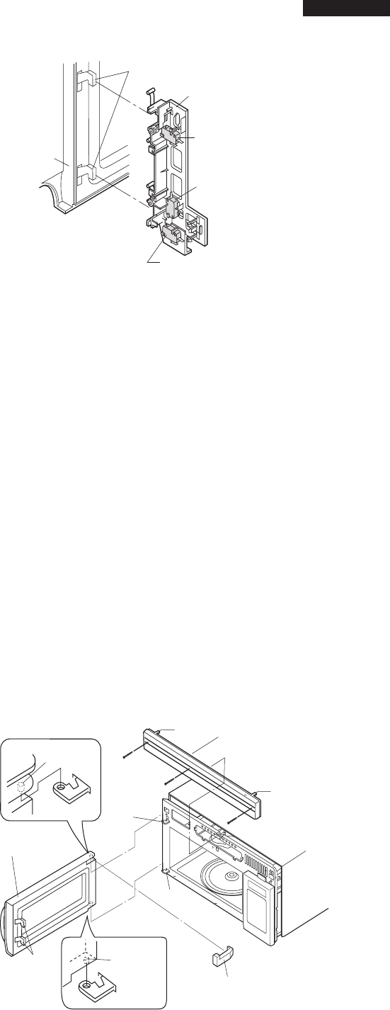
DOOR REPLACEMENTDOOR ASSEMBLY REMOVAL
1. Disconnect the power supply cord.
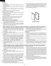
After any servicing, make sure of the following :
1. Door latch heads smoothly catch latch hook through
latch holes and that latch head goes through center of
latch hole.
2. Deviation of door alignment from horizontal line of cavity
face plate is to be less than 1.0mm.
3. Door is positioned with its face pressed toward cavity
face plate.
4. Re-install outer case and check for microwave leakage
around door with an approved microwave survey meter.
(Refer to Microwave Measurement Procedure.)
Note: The door on a microwave oven is designed to
act as an electronic seal preventing the leakage
of microwave energy from oven cavity during
cook cycle. This function does not require that
door be air-tight, moisture (condensation)-tight
or light-tight. Therefore, occasional appearance
of moisture, light or sensing of gentle warm air
movement around oven door is not abnormal
and do not of themselves indicate a leakage of
microwave energy from oven cavity.
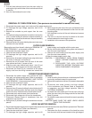
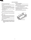
Figure C-2. Door Replacement and adjustment
Latch hook
Door sensing
switch
Latch heads
Monitor switch
Primary interlock switch
Door
Upper Door
Hige Pin
Upper
Oven
Hige
Lower
Oven Hige
Lower Door
Hige Pin
RE-INSTALL
RE-INSTALL
Door Stopper
Door assembly
Latch
Heads
Hood Exhaust Louver
Tab
Tab