


8
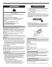
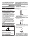
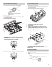
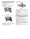
Typical flexible connection
1. Use a combination wrench and pliers to attach the flexible
connector to the adapters. Check that connector is not
kinked.
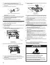
Complete Connection
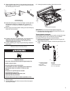
1. Open the manual shutoff valve in the gas supply line. The
valve is open when the handle is parallel to the gas pipe.
2. Test all connections by brushing on an approved noncorrosive
leak-detection solution. Bubbles will show a leak. Correct any
leak found.
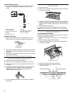
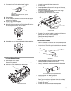
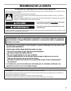
3. Push back on side support rods and slowly lower the cooktop
until it snaps into place.
4. Place burners, burner caps and grates on the cooktop.
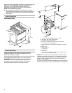
Verify Anti-Tip Bracket Location
1. Make sure the anti-tip bracket is installed
■ Look for the anti-tip bracket securely attached to the floor.
■ Slide the range back so the rear range foot is under the anti-
tip bracket.
2. If installing the range in a mobile home, you must secure the
range to the floor. Any method of securing the range is
adequate as long as it conforms to the standards in the
“Location Requirements” section.
3. Continue installing your range using the follwing installation
instructions.
Level Range
1. Place rack in oven.
2. Place level on rack and check levelness of range, first side to
side; then front to back.
3. If range is not level, pull range forward until rear leveling leg is
removed from the anti-tip bracket. Use ³⁄₈" drive ratchet and
wrench or pliers to adjust leveling legs up or down until range
is level.
4. Push range back into position.
5. Check that rear leveling leg is engaged in anti-tip bracket.
NOTE: Range must be level for satisfactory baking performance.
Check Operation
To Light Standing Pilot Lights:
Before using the range, the standing pilots must be lit. They will
stay lit after turning off the burners.
1. Make sure all controls are off and the oven and cooktop are
cool.
2. Remove surface grates from the cooktop.
3. Lift the cooktop by both front corners until the side support
rods snap into position.
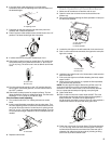
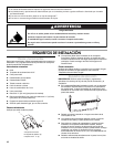
4. Using a match, light both burner pilot lights.
5. The surface pilot flames should be 0.4" to 0.6"
(1.0 to 1.5 cm) high.
A.Pressure regulator
connection fitting
B.Use pipe-joint compound
C.Adapter
D.Flexible connector
E.Adapter
F. Use pipe-joint compound
G. Manual shutoff valve
H.½" or ¾" gas pipe
A.Closed valve
B.Open valve
C
E
G
H
A
D
F
B
A
B
A.Side support rods
A. 0.4" - 0.6" (1.0 - 1.5 cm)
A
A