


Australia
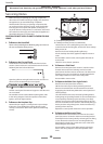
Servicing Notes
Before servicing or replacing gas carrying components,
disconnect the cooker from the gas supply, and check that
the appliance is gas sound following completion.
Likewise, before servicing or replacing components that
are connected to the electricity supply, particularly before
removing the control panel, side panels, cooktop tray, or
any of the electrical components or cover boxes, disconnect
the cooker from this supply, and check that the appliance is
electrically safe prior to reconnection.
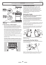
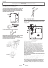
Remove the handrail plastic blanking plugs and remove
the two end bracket fixing screws.
Pull off all the control knobs. Remove the hand rail (see
section 1) Remove the two cross headed screws that were
hidden by the hand rail end brackets.
Open the grill door and right hand oven door and remove
the two screws underneath the control panel.
Pull the control panel forward and support so that the wires
are not strained.
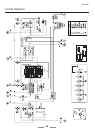
Re-assemble in reverse order. When replacing leads, refer
to the wiring diagram. Check the operation of the timer,
ignition, and oven light switches.
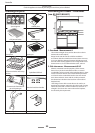
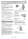
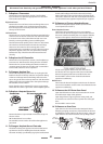
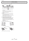
Remove the pan supports, cooktop burner caps and tops.
If there are screws holding the cooktop burners to the
cooktop, remove them (but not the spark electrode fixing
screws).
A Cooktop front fixing screws
B Cooktop rear fixing screws (on cooker back)
Remove the two rear cooktop fixing screws (B) on the
cooker back under the flue grille, and the four front cooktop
fixing screws (A).
Remove the screws holding the flue grille stays.
Lift the cooktop clear of the appliance. Replace in reverse
order.
Re-assemble in reverse order, ensuring that the leads are
reconnected.
Check for correct burner operation.
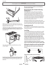
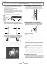
Remove the control panel (see section 2). Pull the cooker
forward. Remove the four retaining screws from each
panel (two at the front and two at the rear). The lower front
retaining screws (one each side) are situated beneath the
lower edge at the front corners of the side panels
Re-assemble in reverse order.
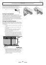
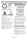
Remove the control panel (see section 2).
NB The old switch may be destroyed during removal.
Remove the switch button and old switch from its bezel
by gripping the switch body behind the control panel and
twisting sharply.
The switch bezel can then be removed by folding back its
locking wings and pushing forward. Fit the new bezel to the
control panel by first lining up the raised key on its body
with the cutout in the control panel and pushing it in from
the front. Assemble the new switch to the bezel by lining up
the key sections and pushing home. Fit the new button by
pushing in from the front.
Replace the control panel and test for correct operation.
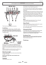
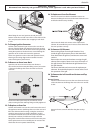
Pull off the timer control buttons and remove the control
panel (see section 2). Remove the timer/mounting bracket
assembly from the control panel by removing the two fixing
screws. Remove the timer from its mounting bracket by
depressing the plastic lugs on the timer case, at the same
time pulling the unit forward.
Re-assemble in reverse order. When replacing the leads,
refer to the wiring diagram. Check the operation of the
timer.