


3-4
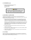
Figure 1. Retainer latches securing filter
pan.
3.7 SYSTEM INSTALLATION INSTRUCTIONS
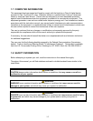
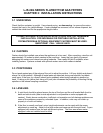
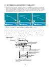
1. This system consists of a 2424G fryer with
a built-in filter and an additional fryer that
will be attached to it. The additional fryer
may be a 24G, an 1824G or a 2424G. If
the additional fryer is an 1824G, the 18-
inch frypot must be in the outside position,
as shown in the illustration below.
The 24-inch frypots must mate with each other.
18-inch frypots, if present, must always be to
the outside of the battery.
24 24
24 182418
Filter Unit
These frypots must mate.
These frypots must mate.
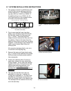
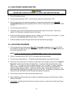
2. Prior to removing the fryers from their
pallets, open the doors of the 2424G with
the filter and unlatch the filter pan locks
(Fig. 1, circles). Disconnect the filter
supply hose and remove the filter pan from
the cabinet. Remove the fryers from the
pallets by lifting them up and over the pallet
supports. Avoid damage to the casters and
caster support bases when lifting and
placing fryers.
All connection hardware (bolts, nuts, etc.)
is included in the shipping bag.
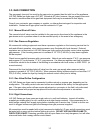
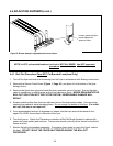
3. Remove the upper and lower back panels
(Fig. 2, arrows) of the cabinets to be joined.
Set the screws and back panels aside for
later reassembly.
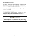
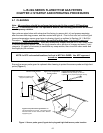
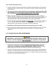
4. Position the cabinets within 6 inches of
each other, close to the area where they
will be installed. Do not push the cabinets
together at this time. Connect the red and
yellow wires exiting the cabinets to be
joined (Fig. 3). The 1824G oil-return
switches will not work if these wires are not
connected.
5. The fryer with the filter has a slip-nut
attached to its drain-tee. Lubricate its
O-rings with vegetable oil. The fryer to be
attached has a drainpipe running from its
drain-tee through a hole in the cabinet side.
This drainpipe will be inserted into the slip-
nut in the next step.
Figure 2. Removing cabinet backs to
access connection points.
Figure 3. Yellow and red wires connecting
oil return switches.