


2-4
After the fryer has been positioned under the exhaust hood, ensure the following has been
accomplished:
1. Adequate means must be provided to limit the movement of fryers without depending upon the
gas line connections. If a flexible gas hose is used, a restraining cable must be connected at all
times when the fryer is in use. The restraining cable and installation instructions are packed with
the flexible hose in the accessories box that was shipped with your unit.
DANGER
Do not attach an apron drainboard to a single fryer. The fryer may become unstable,
tip over, and cause injury. The appliance area must be kept free and clear of
combustible material at all times.
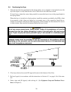
2. Level fryers equipped with legs by screwing out the legs approximately 1 inch then adjusting
them so that the fryer is level and at the proper height in the exhaust hood. Frymaster
recommends that the minimum distance from the flue outlet to the bottom edge of the hood be 24
in. (600 mm) when the appliance consumes more than 120,000 BTU per hour. NOTE: There
are no built-in leveling devices on fryers equipped with casters. The floor where the fryer is to
be installed must be level.
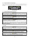
3. Test the fryer electrical system:
a. Plug the fryer electrical cord(s) into a grounded electrical receptacle.
b. Place the power switch in the ON position. Verify that the display indicates CYCL.
c. Place the fryer power switch in the OFF position. Verify that the display indicates OFF.
4. Refer to the data plate on the inside of the fryer door to determine if the fryer burner is configured
for the proper type of gas before connecting the fryer quick-disconnect device or piping from the
gas supply line.
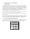
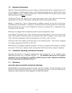
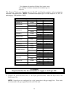
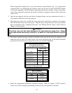
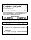
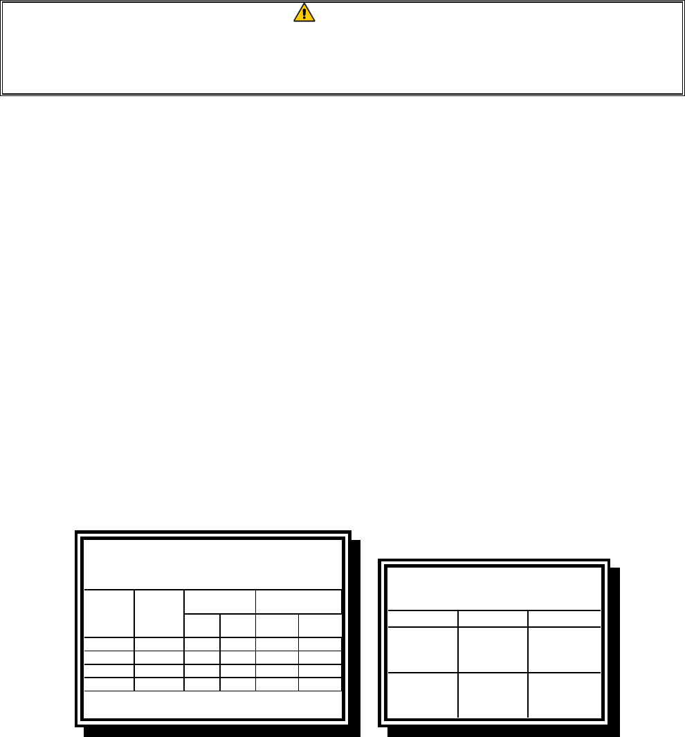
5. Verify the minimum and maximum gas supply pressures for the type of gas to be used in
accordance with the accompanying tables.
Orifice Diameter
Singl
e
Vat
Dual
Vat
Singl
e
Vat
Dual
Vat
G20 20 2 x 3.40 2 x 3.40 7 mbar 7 mbar
G25 20 or 25 2 x 3.40 2 x 3.40 10 mbar 10 mbar
G30 28/30 or 50 2 x 2.05 2 x 2.05 17 mbar 17 mbar
G31 37 or 50 2 x 2.05 2 x 2.05 20 mbar 20 mbar
CE Standard
for Incoming Gas Pressures
for Fryers Manufactured After April 1999
(
1
)
mbar = 10,2 mm H
2
O
Gas
Pressure
(mbar)
(1)
Regulator Pressure
Non-CE Standard
for Incoming Gas Pressures
Gas Minimum Maximum
Natural
6" W.C.
1.49 kPa
14.93 mbar
14" W.C.
3.48 kPa
34.84 mbar
LP
11" W.C.
2.74 kPa
27.37 mbar
14" W.C.
3.48 kPa
34.84 mbar
6. For fryers equipped with a FootPrint Pro system or basket lifts, plug the electrical cord(s) into a
power receptacle behind the fryer.