


1-2
ignition by measuring the flow of microamps through the flame. If the burner does not light (or is
extinguished), current to the ignition module is cut, the gas valve closes, and the ignition module
“locks out” until the power switch is turned off and then back on. A probe monitors the temperature
in the frypot. When the programmed setpoint temperature is reached, resistance in the probe causes
the heat cycle circuitry in the computer to cut off current flow through the heat relay. This in turn
cuts off the 24 VAC to the ignition module, causing the gas valve to close.
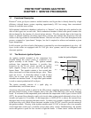
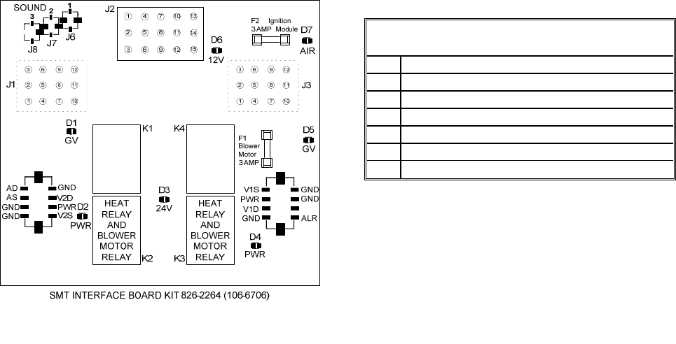
1.3 Interface Board
All fryers in this series have an interface board located in the component box behind the control
panel. The interface board provides a link between the computer and the fryer’s individual
components without requiring excessive wiring, and allows the computer to execute commands from
one central point.
K2 and K3 are double-pole-double throw (DPDT) relays that supply 24VAC to the ignition and gas
valve circuits, as well as 120VAC to the blower motor. The relays on this board plug into sockets.
If a relay fails, that relay can be replaced.
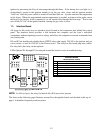
LEDs (labeled D1 through D7) are arrayed around the board to assist in troubleshooting.
D1 24 VAC to left gas valve (dual vat only)
D2 24 VAC to left ignition module (dual vat only)
D3 24 VAC from transformer
D4 24 VAC to right ignition module
D5 24 VAC to gas valve (right valve if dual vat)
D6 12 VAC from transformer
D7 CE and Japanese units only: air switch closed
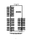
INTERFACE BOARD
LED DIAGNOSTIC LIGHTS
NOTE: In full-vat fryers, the relay for the left side (K2) may not be present.
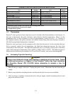
The chart on the following page illustrates current flow through the board, and the table at the top of
page 1-4 identifies frequently used test points.