


TB14 SERIES GAS FRYERS
CHAPTER 3: INSTALLATION
3-6
3.4 Gas Connections (cont.)
3. If disconnection of the restraint is necessary, this restraint must be reconnected after the
fryer has been returned to its originally installed position.
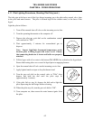
J. After hook-up, bleed the gas line of air to ensure that the pilot light will ignite quickly.
K. CE Standards: If the unit is to be installed with flexible coupling, use a commercial flexible
coupling certified as NF D 36123 (or other national standard) or a quick disconnect device
certified NF D 36124 (or other national standard).
3.5 Electrical Connections
The fryer when installed must be electrically grounded in accordance with local codes, or in the
absence of local codes, with the National Electrical Code, ANSI/NFPA 70-(latest edition).
DANGER
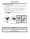
This fryer is equipped with a three-prong (grounding) plug for protection against
electrical shock and must be plugged directly into a properly grounded, three-prong
receptacle. DO NOT CUT, REMOVE, OR OTHERWISE BYPASS THE GROUNDING
PRONG ON THIS PLUG!
The rating plate and wiring diagram are located inside the front door. The fryer is equipped with a
120VAC single-phase 60-hertz system (Domestic), or 230VAC single-phase 50-hertz system
(International/CE). Do not cut or remove the ground prong from the power cord plug. Do not
attempt to use the fryer during a power outage.
DANGER
This appliance requires electrical power for operation. Place the gas control valve in
the OFF position in case of a prolonged power outage. Do not attempt to operate
this appliance during a power outage.