


YSCFC SERIES FLATBOTTOM GAS FRYERS
CHAPTER 1: SERVICE PROCEDURES
1-8
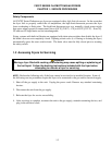
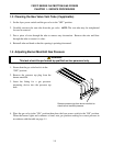
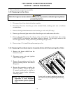
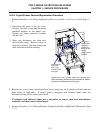
11. Reverse steps to install new temperature probe or high-limit. If reinstalling high-limit, ensure the
capillary tube is properly routed around the temperature probe before tightening (see photo, Step
#8). Reconnect wiring removed from defective high-limit.
IMPORTANT (High-Limit): When installing new high-limit, ensure the capillary tube and
bulb are positioned properly with the mounting hardware installed prior to tightening the
compression nut. Once tightened, the capillary tube cannot be repositioned.
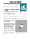
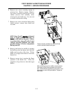
IMPORTANT (Temperature Probe):
When installing new temperature probe,
ensure probe is positioned properly with the
mounting hardware installed (current
production systems), or 1/8" from frypot
bottom (older systems), prior
to tightening
the compression nut. Once tightened, the
probe cannot be repositioned.
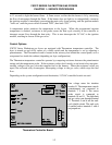
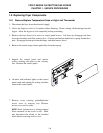
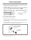
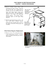
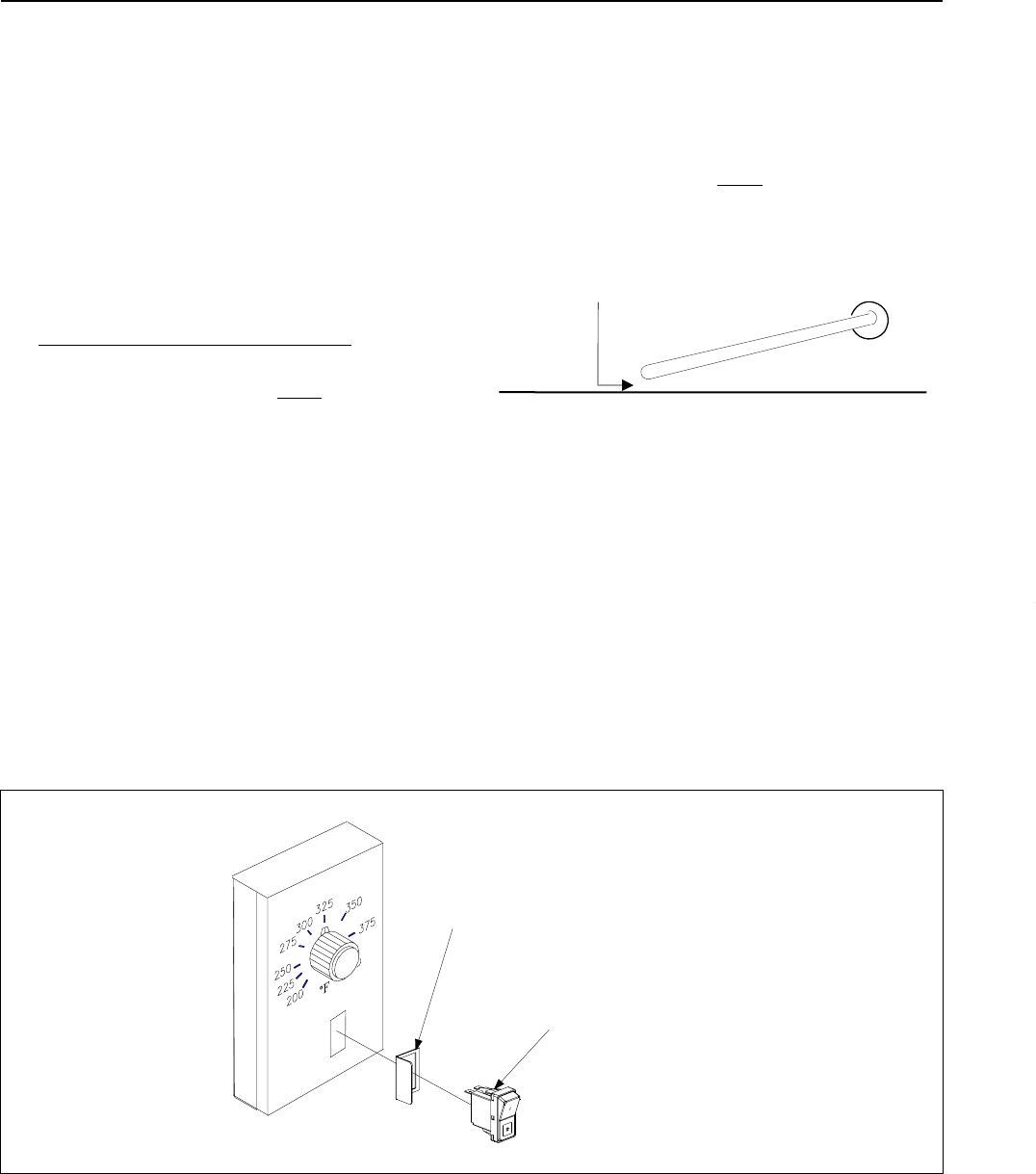
1.6.2 Removing/Replacing Rocker Switches
1. Disconnect the fryer from the electrical supply.
2. The switches are located on a control box inside the unit. Remove the screws securing the front
panel of the control box. Do not allow the panel to hang by the switch wiring harness wiring;
use some type of support.
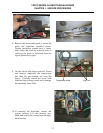
3. Depress the retaining clips (see illustration below) and push the switch out of the slot. If there is
a switch-guard present, retain it for installation of the replacement switch.
Depress clips on each
end to remove switch
from control panel.
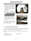
When connecting wires to replacement
switch, pass the wires through the
switch guard (if applicable) before
connecting to switch.
4. Remove wires one at a time from the switch being removed and connect to the replacement
switch until all wires are transferred.
In older fryers, ensure probe tip is 1/8" from
frypot bottom for proper temperature sensing.
Frypot Bottom