


YSCFC SERIES FLATBOTTOM GAS FRYERS
CHAPTER 1: SERVICE PROCEDURES
1-10
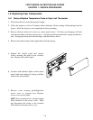
1.6.5 Removing/Replacing Blower Assembly or Air Prover Switch
1. Remove back panel. On systems with built-
in filtration, use care not to damage the oil-
return heat-tape wiring insulation when
removing backs (multi-batteried systems after
02/03 have two-piece back panels; remove
both to access blower assembly).
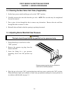
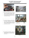
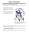
2. Remove blower assembly by removing four
screws (two screws securing the flue outlet to
the firebox, and two screws securing the
blower inlet housing to the firebox). Pull the
assembly out of the slot and lower to the side.
Do not remove the electrical connections at
this time.
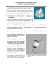
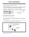
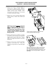
3. Remove junction box cover and mark and
disconnect wiring to the switch. Unscrew
fitting connecting sampling tube to air prover
switch, being careful not to kink the tube.
Remove two screws from bracket that
attaches switch to junction box to remove
switch. Install new air prover switch with
bracket. Reattach sampling tube and wires
removed from old switch and replace
junction box cover.
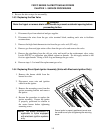
4. If replacing blower, remove junction box
cover, mark and disconnect each wire, and
remove conduit fitting from junction box.
Reinstall conduit fitting on new blower
and reconnect wiring. Replace box cover.
5. Reverse steps 1 – 2 to reinstall blower
assembly.
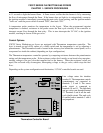
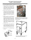
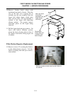
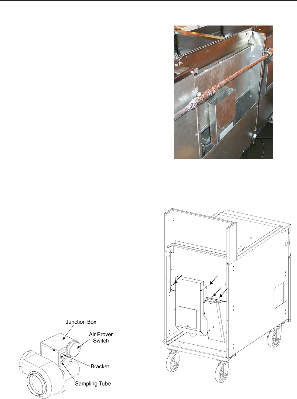
Multi-batteried systems after have upper and lower
back panels, which must be removed to access the
blower assembly. (fryer at left shown with upper
back
p
anel removed
)
.
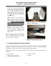
After removing screws (arrows), remove blower
assembly from firebox by pulling outward.