


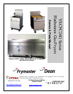

YSCFC SERIES FLATBOTTOM GAS FRYERS
CHAPTER 1: SERVICE PROCEDURES
1-1
1.1 Functional Description
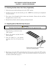
YSCFC Series Flatbottom gas fryers contain a welded steel frypot (mild steel) with heat-transfer
ducting on the frypot bottom for efficient heating of oil without scorching. A draft inducer draws air
over the burners for combustion. Air movement directs the combustion products back and forth
across the frypot bottom by means of a set of baffles, transferring the heat evenly. Cold air is
prevented from entering the combustion chamber and cooling the oil during the coasting cycle.
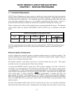
Flames originate from orifices in three tubular burners positioned beneath the frypot. The diameter
of the orifices differs for Natural (CE:G20/G25) and LP (CE:G31) gas as indicated in the table
below.
NON-CE (Altitudes of 2000 feet or less)
EQUIPMENT
PRESSURE
MODEL
INPUT
(BTU)
GAS TYPE
ORIFICE
[DRILL SIZE (MM)]
ORIFICE
PART #
QTY
MBAR INCH W.C.
1824/24YSCFC 120
NAT
LP
#34 (2.82)
#50 (1.78)
810-2051
810-2317
3
3
10
27.5
4
11
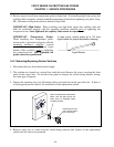
An electromechanical gas valve regulates gas flow to the manifold. YSCFC Series Flatbottom gas
fryers are equipped with a 24-volt valve system and an electronic ignition system (direct spark
ignition).
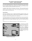
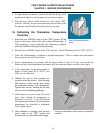
Electronic Ignition Configuration
In units configured for electronic ignition, an ignition module connects to an ignitor assembly. The
ignition module performs three important functions: it provides an ignition spark, supplies voltage to
the gas valve, and proofs the burner flame.
The module contains a time delay circuit and a coil that activates the gas valve. The ignitor
assembly consists of a spark plug and a flame sensor element.
At start-up the ON/OFF switch is placed in the "ON" position, supplying 115 VAC or 230 VAC,
according to system configuration, to the Thermatron interface board. The voltage is stepped down
via transformer to 24 VAC before entering the ignition module. If resistance in the temperature
probe indicates the temperature in the frypot is below 150°F (66°C), the current flows through a melt
cycle circuit where a switch alternately closes for approximately 4 seconds and opens for
approximately 20 seconds. If the temperature is 150°F (66°C) or above, the current flows through a
heat circuit, bypassing the timer switch. In either case, current is supplied to the other leg of the heat
relay coil, which then closes an electronic switch in the 24 VAC circuit to provide current to the
ignition module.
Circuitry in the ignition module sends 24 VAC current to the gas valve via a normally closed high-
limit switch and a drain safety switch. Simultaneously, the module causes the ignitor to spark for up