


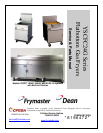
YSCFC SERIES FLATBOTTOM GAS FRYERS
CHAPTER 1: SERVICE PROCEDURES
1-2
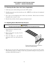
to 11 seconds to light the burner flame. A flame sensor verifies that the burner is lit by measuring
the flow of microamps through the flame. If the burner does not light (or is extinguished), current to
the ignition module is interrupted, preventing the main valve from opening, and the ignition module
"locks out" until the power switch is turned "OFF", then back "ON".
A temperature probe monitors the temperature in the frypot. When the programmed setpoint
temperature is reached, resistance in the probe causes the heat cycle circuitry in the controller to
interrupt current flow through the heat relay. This in turn interrupts the 24 VAC to the ignition
module, resulting in closure of the gas valve.
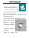
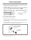
Control Options
YSCFC Series Flatbottom gas fryers are equipped with Thermatron temperature controller. The
fryer is turned on and off by means of a rocker switch and the temperature is set by adjusting a
potentiometer. The Thermatron board is located in the wireway box behind the control panel, or in a
component box inside the cabinet (depending on fryer configuration).
The Thermatron temperature controller operates by comparing resistance between the potentiometer
setting and the temperature probe. If the resistance values don’t match, an on-board relay energizes,
sending voltage to the gas valve that supplies fuel to the burners. When the resistance values are
equal, the on-board relay de-energizes, interrupting voltage to the gas valve, which stops the fuel
flow.
Depending on the system configuration and destination, 115VAC controller boards are used.
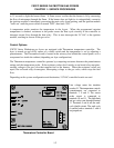
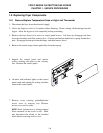
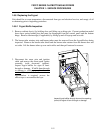
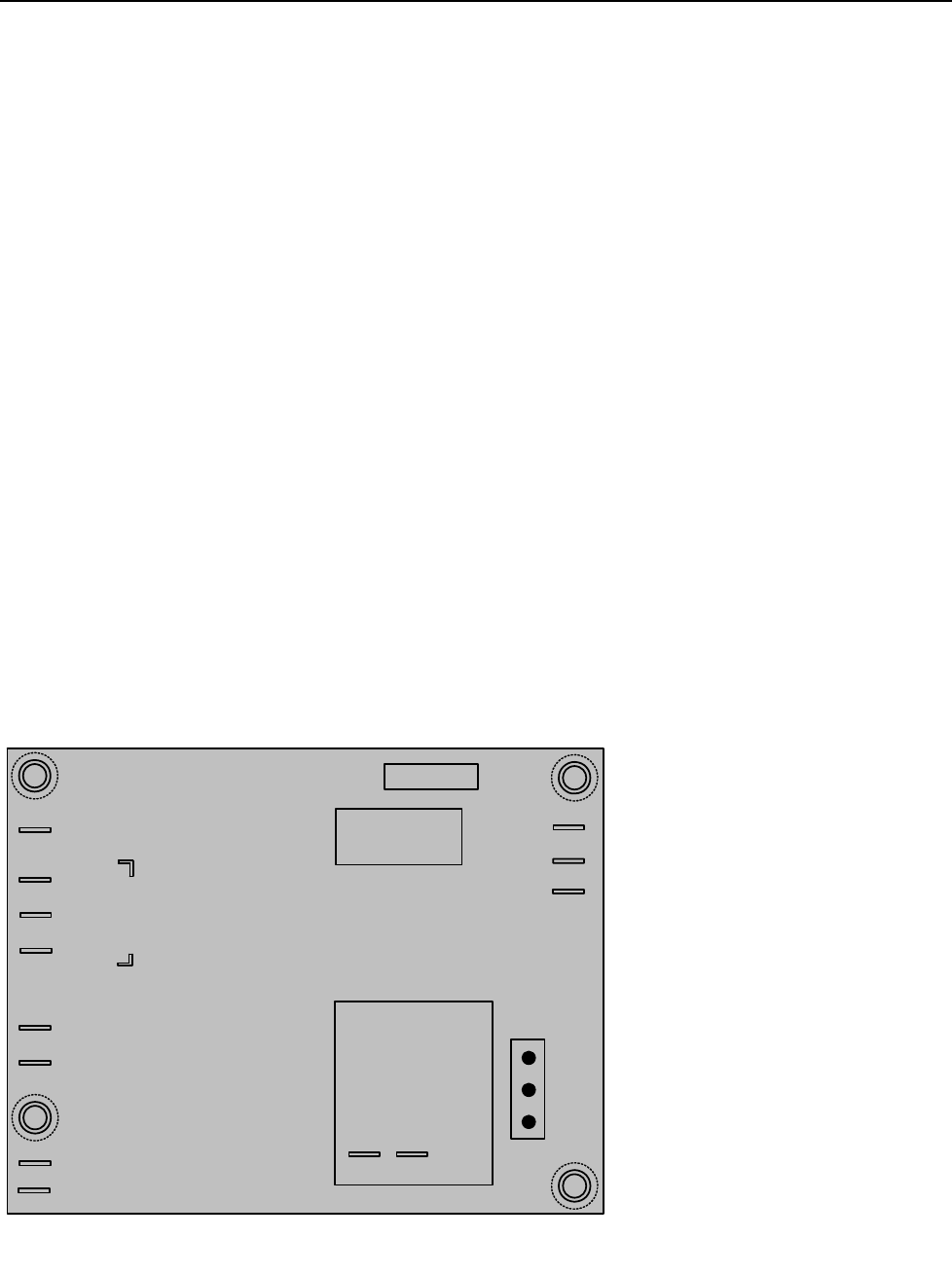
Line voltage enters the interface
board at J1. The temperature controls
(potentiometer) are connected to
terminals 7, 8 and 9. The sensor
probe circuit is connected to
terminals 10 and 11. The high-limit
and gas valve route through terminal
12. Terminals 5 and 6 are the melt-
cycle disable circuit. The melt cycle
is enabled unless terminals 5 and 6
are jumped out.
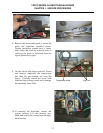
Thermatron Controller Board
MELT CYCLE DISABLE
6
5
PROBE
10
11
COM
13
NC
14
7
8
9
EXT POT
115
230
COM
BOIL
12/24 VAC INPUT
P12 P13
CT
CCW
CW
NO
12
3 AMP FUSE
REMOVABLE
RELAY
F1
K1
J1