Part # 4520898 (03/31/11)Page 12
INSTALLATION continued
Unit Placement
After the cut out has been made according to the previous
sections, apply silicone to the top of the counter and press
the induction unit into the silicone, allowing for a complete
water tight seal between the unit and the counter. Make sure
the unit is level.
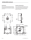
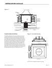
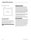
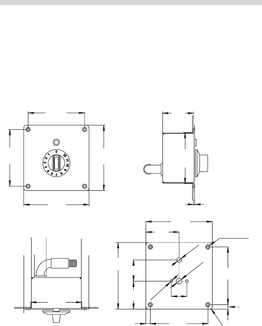
Installation of Operating Unit
Each unit is supplied with a complete operating unit. In order
to x this unit on the surface of the enclosure, a cut out for
the power switch and the LED must considered. The operator
control panel has to be xed vertically on the installation
panel. The cable for the power switch and the LED have a
length of 39.37” (1000mm).
4.09"
[104mm]
4.09"
[104mm]
4.72"
[120mm]
4.72"
[120mm]
0"
0.55"
[14mm]
0.75"
[19mm]
1.73"
[44mm]
4.17"
[106mm]
4.72"
[120mm]
3.66"
[93mm]
2.24"
[57mm]
3.66"
[93mm]
0.08"
[2mm]
4.72"
[120mm]
4.72"
[120mm]
2.36"
[60mm]
1.50"
[38mm]
1.99"
[50.5mm]
0.31"
[8mm]
0.31"
[8mm]
4x R 0.20"[5mm]
4X counter sunk
ø 0.31"x ø 0.18"
[ø 8mm x ø 4.5mm]
4.09"
[104mm]
4.09"
[104mm]
1.10"
[28mm]
2X ø 0.20"
[ø 5mm]
ø 0.40"
[ø 10.2mm]
ø 0.33"
[ø 8.5mm]


