


Part #GCGTRAINING06 (03/03/08))Page 10
Thermostat
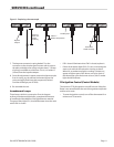
Make sure the thermostat knob is correctly aligned with
the dial indicator. To align the knob with the graduated dial
correctly, follow this procedure.
1. Turn the knob and shaft fully counter-clockwise. Loosen
the set screw in the knob and align the pointer with the
rst line of the scale at the lower left position.
NOTE : When the knob is fully rotated clockwise, the pointer
should align with the last line of the scale.
2. Set the dial to 350˚F. Wait at least three cycles before
monitoring the temperature.
3. Use a surface temperature probe disc positioned on the
center line with the thermostat knob and centered front
to back on the griddle plate.
The thermostat will overshoot and undershoot as caused
by the lag time in the thermal response of the heat source-
to-plate and plate-to-sensor. The calibration temperature
will be the mid-point between the minimum and maximum
readings. Other than the alignment of the knob pointer,
there is no means to calibrate the thermostat. It has been
precisely calibrated by the manufacturer.
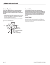
Thermocouple
If the temperature is incorrect check the thermocouple.
The thermocouple in this unit is a Type J, which requires
the use of a J-type temperature meter for checking. For a
complete understanding of the thermocouple used in the
chain griddle see the GCR Service Bulletin #95-5 entitled
“Thermocouples”.
A thermocouple is an accurate temperature measuring
device that consists of two dissimilar conductors joined
together at their ends. It works on a simple principle, which
is that the thermoelectric voltage between the two junctions
is proportional to the temperature dierence between them.
This principle is applied to measure the temperature at one
of the junctions when the other is held at a xed known
temperature. The technology is not new, but its use in GCR
griddles is recent.
The thermocouple probe is embedded in the griddle plate
and accurately registers the surface temperature. It is a
reliable device, but can cause problems when it fails for any
reason. In addition to deterioration from aging, it can fail in
two ways: one from an open-circuit (that is, a break in one of
its wired); the other when it short-circuits.
If a thermocouple open circuits, the thermostat will shut o
and prevent the gas valve from opening, which means the
burner will not function.
If a unit short circuits somewhere behind the junction, it
creates a new junction and because the circuit cannot detect
the existence of a short circuit fault, there is a dramatic
increase in temperature. The thermocouple detects changes
in temperature, but because of the short circuit it may fail to
register the set temperature at the thermostat. This means
the burner may not shut o. At the other extreme, the short
circuit may occur in a place not shielded from the ue gases,
which means the burner may shut o prematurely. These are
the two conditions to look for in a shorted thermocouple.
Deterioration from aging and from welding dissimilar metals
together to for a junction introduces a contaminant that
causes mechanical stress. Over time, ve to ten years, metal
fatigue from aging is certain. As a result, the temperature
curve will vary.
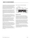
How To Replace A Thermocouple
A heat shield protects the thermocouple from the burner
ames and ue gases. Without the shield, the thermocouple
would register ame heat to the thermostat instead of
sensing the temperature of the griddle plate.
To replace a thermocouple (refer to Figure 3), following this
procedure:
1. Open the front panel to get access to the terminal board.
2. To withdraw the thermocouple, rst remove the heat
shield. It is held in place by two combination Philip
and Robinson-heat size number 10 sheet metal screws.
Remove the heat shield by sliding it down the wire.
3. A bayonet connector secures the thermocouple in place.
Reach inside the hole and push and twist the bayonet
connector a quarter turn.
4. Remove the connection to the terminal board and feed
these wires through the heat shield. The thermocouple is
now removed.
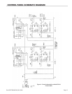
5. Connect the wires of the replacement thermocouple, but
make sure the polarity is correct. Connect the negative
red wires to terminal 7 on the thermostat and the positive
white wire to terminal 8. (See schematic diagram).
6. Thread the thermocouple through the heat shield and
into the plate cavity.
SERVICING continued