


Part #GCGTRAINING06 (03/03/08) Page 9
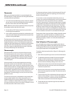
SERVICING
Many factors aect the serviceability of equipment. In the
chain griddle, there are more components to service than in
older models. The new griddle is a compact design. Access
to the temperature control circuitry and ignition units is
easy. Service techniques for the thermocouple will vary
depending on the model type.
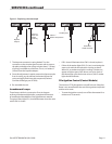
They unit is available with a 6” (152mm) leg which means
that under the griddle plate there is only 6” (152mm) of
working room. To replace a thermocouple it is dicult to
lift the griddle plate, rmly secured to the support frame. To
replace a thermocouple requires bottom access because the
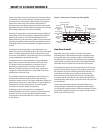
plate is securely xed (see Figure 3).
With this introduction to serviceability, and apart from
the features that make the chain griddle superior to more
conventional units, many of the servicing tasks are standard;
the adjustments likewise. The procedures that follow are
a plain guide to servicing, beginning with adjustments to
various components.
Have The Right Tools And Instruments
In addition to a service technician’s normal hand tools, for
servicing this chain griddle we recommend:
1. A manometer or other suitable instrument for measuring
gas pressure
2. A multimeter
3. A digital read-out temperature meter
4 A micro-ammeter
CAUTION : In this chain griddle we use a J-type
thermocouple, which requires a meter with a J-type
connection for checking. Most meters have K-type
connections.
Adjustments
Every griddle is inspected and tested before it leaves the
factory. Adjustments to the unit during installation and
servicing are the responsibility of the eld operator and are
not considered to be defects in material or workmanship.
For this reason, adjustments are not covered under the
equipment warranty.
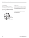
Pilot Flame Adjustment
A pilot adjustment valve is in the line form each pilot
combination valve and access to it is behind the lower front
panel.
1. To remove the upper front and lower front panels, refer to
the installation procedure given earlier.
2. To reduce the volume of gas feed to the pilot, turn the
small screw in the pilot adjusting valve clockwise.
3. To increase the gas feed to the pilot, turn the same screw
counter-clockwise.
NOTE : Adjust the gas feed to produce a 7/16” (11mm) long
ame to make sure the ame envelopes the top of the ame
sensor.
Burner Air
Make sure a burner is warm before adjusting the air shutters
and follow this procedure.
1. First, loosen the screw along the side of the burner near
the orice.
2. A burner ame that gets too much air appears to lift
above the burner as though separated from it. This
means the shutter needs throttling back to a more closed
position.
3. A yellow tip on the ame is a sign that the shutter is
not passing enough air to feed the ame. In this case, it
necessary to open the shutter.
4. When the shutter adjustment is complete, tighten the
screw to lock the shutter setting in the adjusted position.
5. Re-close the upper and lower front panels and replace
the fasteners.
Removing the Griddle Plate
If it is necessary to remove the griddle top, follow this
procedure:
1. Disconnect the power supply.
2. Remove the upper control panel.
3. Open the lower control panel.
4. Disconnect all thermocouple sensors and shield bayonet
adapters. (To reassemble, see the Thermocouple section.)
5. Remove the griddle top retaining bolts (both left and
right).
6. Remove the back ue.
7. The griddle top is now easily removed.