


Part #GCGTRAINING06 (03/03/08))Page 12
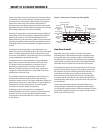
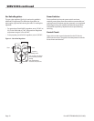
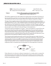
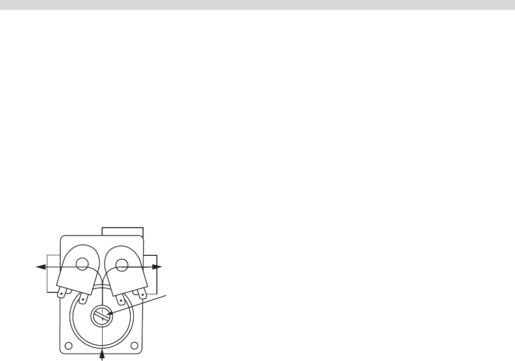
Gas Valve Regulator
The gas valve regulator (See g 4) used on the griddle is
AGA and CGA approved. The direction of gas ow is at
right angles, right and left viewing the inlet. For setting the
regulator:
• For natural gas, Part #240510 regulator, set at 3.5” W.C. at
22 CFH air each side at 7” W.C. inlet pressure. Regulator
adjustment range is 2.8” to 4.0” WC.
• From propane, part # 245101 regulator, set at 10.0” W.C.
Figure 4 – Gas Valve Regulator
Flow
Flow
Pressure
setting screw
Turn counter-clockwise
to increas the pressure
setting
Turn clockwise to
decrease the pressure
Inlet
Power Switches
Dust caps tted on the main power switch and zone
switches protect them from dust and the corrosive eect of
cooking fumes. If the dust caps are removed, or not replaced
following servicing, the switches will deteriorate and have
reduced life expectancy. Replace the dust caps following
servicing.
Control Circuit
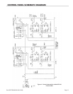
Figure 4 shows the control schematic for the GC-48 unit,
which has two zones. The ignition and temperature controls
for each zone are identical.
SERVICING continued