


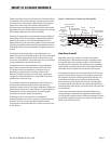


Part #GCGTRAINING06 (03/03/08) Page 7
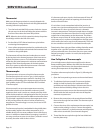
• Each thermostat controls one zone burner though a
dual solenoid-pressure regulator valve complete with a
pressure test spigot. Check the manifold gas pressure on
each combination valve to make sure it is the same as
that shown on the serial plate. The gas pressure should be
3.5” WC for natural gas and 10.0” for propane gas.
• For access to the pressure test spigots, turn the main
power switch and all zone power switches to the OFF
position and lower the front panel on its hinge. This is a
safety precaution. The test spigots are at the rear of the rear
of the combination regulator valves.
• Connect your manometer to the rst valve for test and
turn the manual shut-o valve to the ON position.
NOTE : The shut o valve is under the unit. When it is ON and
in the open position, the valve position is in line with the
piping. Also, see the electrical procedure below for notes on
the status indictor lights and setting the thermostats.
• Turn the main power switch and the zone power switches
to the ON position.
• Set all the thermostat dials to 350˚F. When all the burners
are operating, check and record the manometer reading,
which should be the same manifold pressure as that
specied on the serial plate (3.5” WC for natural gas and
10.0” for propane gas). Adjust the regulator to obtain the
pressure rate specied.
• When satised with the reading obtained, turn the main
power switch OFF. Remove the manometer test tube and
re-cap the test spigot.
• Repeat this operation on each combination regulator
valve to correctly set it. Then turn each thermostat, zone
and main power switch OFF.
Electrical Power, Lighting & Control
WARNING : Do not work on ungrounded equipment. It is
dangerous.
• National and local electrical codes require that all devices
of this type be electrically grounded. Check to make sure
the unit is grounded.
CAUTION : Make sure the electrical connections enclosed by
the panels are in good order and undamaged before closing
and securing the front panels.
NOTE : This griddle is equipped with a 3-pronged plug cord
set to t any 120V AC3-prong, 15 amp-rated, grounded
receptacle.
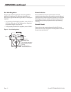
• To check the unit lighting, turn the main power switch of
the unit to the ON position. The green light of the power
switch and the green indictor of the gas pilot of each
section of the griddle should illuminate.
CAUTION : If after two minutes the pilot ignition fails, turn
the main power switch OFF. Wait ve minutes and switch the
main power ON again.
• When the green indicator for each zone is illuminated,
turn the zone power switch for each zone ON. The
thermostats can now be set to the desired temperature.
• The amber light burner indicator cycles with the
operation of the thermostat.
Ventilation
For ecient operation this unit requires a minimum
ventilation air supply of 50frm. The ideal method of
ventilation is a well-designed canopy of hood that exceeds 6”
(152mm) beyond all sides of the unit. Ideally, the bottom of
the hood should be set 6’6” (1981mm) from the oor.
Gas burners and pilot devices need a sucient air supply to
operate eciently, so do not place large objects anywhere
near them to restrict or in any way limit the air ow.
In most operations, the chain griddle will be used in
conjunction with other kitchen equipment. The need for
the ingress of air to the kitchen area must be sucient to
compensate for the air the ventilation system abstracts.
Unless the air ow is sucient a subnormal, and probable
negative, atmospheric pressure will result, which will
adversely aect the operation of the equipment and make
work in the kitchen area unpleasant.
Start-Up
When the chain griddle is used for the rst time, the griddle
top requires seasoning. To season a griddle surface, follow
this procedure.
1. Wash the griddle surface with a hot, mild detergent or
soap solution, then rinse and dry thoroughly.
2. Set the thermostat to 175˚F for 30 minutes, then apply a
lm of cooking oil to the cooking surface and wipe away
the excess.
3. After (5) ve minutes, wipe the griddle plate clean.
INSTALLATION continued