


Part #GCGTRAINING06 (03/03/08))Page 6
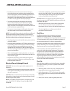
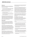
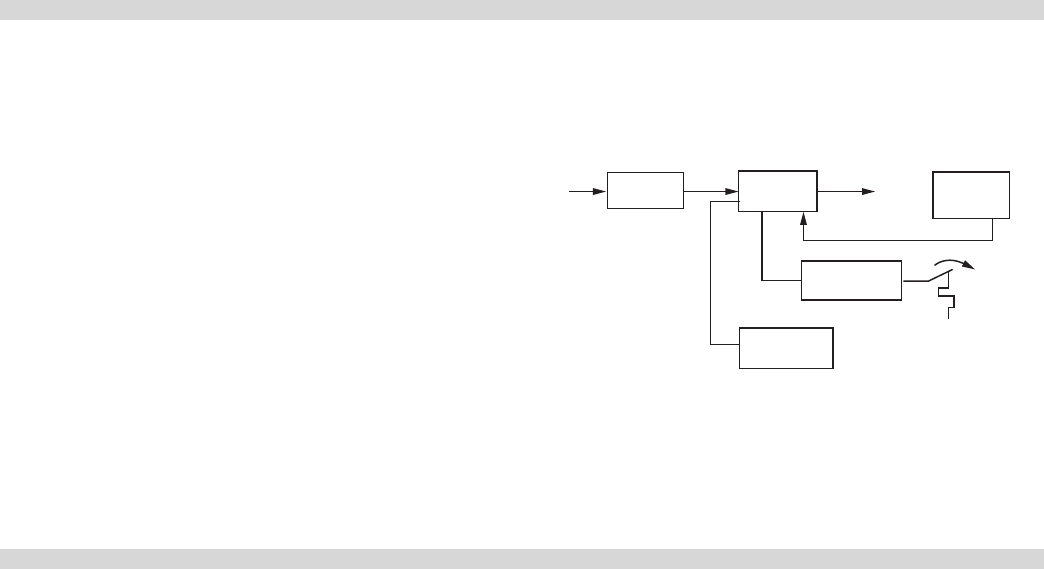
During normal operation, the pilot ame is continually
monitored. The ame current signal must maintain 0.15
microamps minimum. Flame failure response time is 0.8
seconds maximum. If at any time the ignition module does
not detect a pilot ame, it will repeat the ignition process by
allowing a 50 second trial of ignition.
Figure 2 illustrates this sequence of operation.
Figure 2 – Sequence of Operation
Power
Ignition
Spark
o/p
Flame
sensor
Pilot valve
Main valve
INSTALLATION
The instructions given for installation form part of the
delivery package. Anyone installing a chain griddle should
follow a strict procedure to make sure installation and
commission are safe, ecient and complies with the
applicable local codes. Here is a check list of things to do in
the order we recommend.
Mechanical
• Uncrate and check for shipping damage both obvious
and hidden. Write a damage report and report
immediately to the carrier.
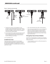
• Check the serial plate behind the front panel. To do this,
remove the front panel by unscrewing the two screws in
the upper right and left corners. Next unscrew the two
fasteners securing the hinged lower font panel in place.
Note the burner inputs shown on the serial number
plate. It may be necessary to refer to these later. You also
need to be certain of the type of gas to which the unit
is connected. The serial plate also species the type of
gas required for the unit. Also, check that the electrical
connections are in good order.
NOTE : The chain griddle is certied for installation on a
combustible base with minimum clearance of 6” (152mm)
back and 6” (152mm) sides from combustible walls.
• Every unit is tted with a readily accessible shut-o valve
at the main manifold. Use a minimum of 3/4” NPT pipe to
connect the incoming gas supply.
CAUTION : Check the pipe capacity tables given in the
installation code. When a long supply pipe run is necessary,
you may have to install a supply line lager than 3/4”
• Have a qualied gas technician check the gas supply to
make sure it will deliver the BTUs of gas the unit requires
to operate with no more than 1/2” water pressure
drop. Also when making this check be certain that all
equipment on the gas line is turned to the ON position.
• If you are installing the unit using a new gas installation,
make sure the supply lines have been cleaned and
purged of piping compound, chips and other debris.
WARNING : Use soap solution if you have to check the gas
lines for leaks.
• Place and install the unit on the legs or caters provided,
and make sure there is a minimum of 4” (102mm) air
space below the unit for adequate air ow to the burners.
CAUTION: Check for obstructions or objects that could
restrict the air ow to the burners.
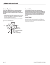
• Using a spirit level variously across the front, rear and sides
of the unit, level it by adjusting the leveling legs.
Gas Supply
NOTE : For ecient operation, the griddle plate must be
level.
WHAT IS A CHAIN GRIDDLE continued