


Part # 4525958 (05/15/09) Page 9
INSTALLATION continued
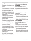
Leg Installation
1. All units are shipped with N.S.F. approved legs. These legs
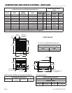
must be installed to provide a minimum clearance of
four (4) inches between the counter top and bottom of
the unit in order to meet National Sanitation Foundation
requirements.
2. When using the legs described above, raise front of unit
and screw leg into leg retaining nut provided at each
corner of unit, repeat at rear.
3. Unit may be leveled by adjusting legs. Use a spirit level
and level unit (by cooking grids) four (4) ways: across the
front and back and down the sides.
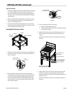
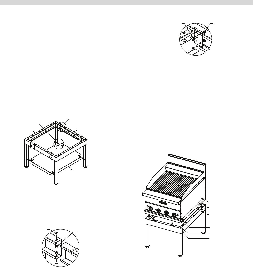
Assembly Of Counter Stand
SLEEVE ASSEMBLY
SHELF
SIDE LEG
ASSEMBLY
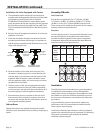
DETAIL 2
DETAIL 1
1. Slide the side leg assembly into the sleeve assembly and
fasten with a screw and a nut in 8 places (2 per joint) as
shown in detail 1.
DETAIL 1
10-24 X 3/8"
MACHINE SCREW
10-24
LOCK NUT
2. Place the center support bracket inside of the sleeve
assembly. Mount the center support to the bracket with
2 screws and nuts (detail 2). Repeat for the other side.
Sleeve assemblies should be sandwiched between the
center support and center support bracket. Repeat for
other center support.
10-24 X 3/8"
MACHINE SCREW
10-24
LOCK NUT
CENTER
SUPPORT
BRACKET
DETAIL 2
3. Prior to placing the unit on the stand:
a. Remove levelling feet from unit.
b. Remove grates/rods/burners etc. to lighten unit and
team lift onto stand.
4. Attach the broiler to the stand at the back with (2) 1/4”
bolts, washers and lock nuts as shown. (One for each
corner.)
NOTE: for 48” broiler there are (4) mounting locations at
the back.
1/4-20 LOCK NUT
1/4 WASHER
1/4-20 X 5/8 BOLT
FASTER ON BROILER
3/8 LOCK WASHER
3/8-16 X 5/8 BOLT
GF24 BROILER STAND
WITH LEGS SHOWN
5. Attach the broiler to the stand at the front with (2) 3/8”
bolts & lock washers as shown. Bolt with thread into
fasteners attached to the bottom side of the broiler (one
for each corner).
NOTE: for 48” broiler there are (4) mounting locations at
the back.