


Part # 1382698 (02/26/08) Page 5
INSTALLATION
Clearances
The appliance area must be kept free and clear of all
combustibles.
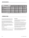
These units are design-certied for the following
installations:
1. Intended for other than household use.
2. For use in non combustible locations only.
3. For use with 4” (minimum) legs.
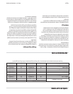
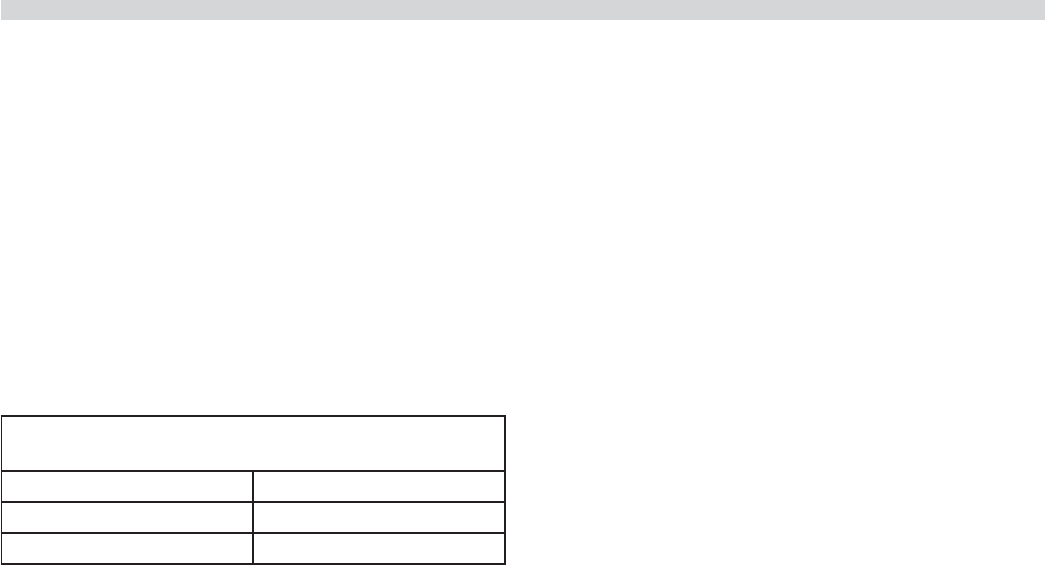
Type of Construction
Minimum Clearance
Combustible Non-Combustible
Rear 3” (76mm) Rear 0”
Sides 6” (152mm) Sides 0”
Positioning and Setup
The hot plate should be placed on a solid, level countertop
with ample space to combustible surfaces, as dened under
“CLEARANCES.”
The unit should be leveled with a carpenter’s spirit level from
front to back and side to side. Each leg features an adjustable
foot which can be screwed in or out to facilitate leveling.
Air Supply and Ventilation
The area around the appliance must be kept clear to avoid
any obstruction to the ow of combustion and ventilation
air, as well as, for ease of maintenance and service.
Means must be provided for any commercial, heavy-duty
cooking appliance to exhaust combustion waste products to
the outside of the building. Usual practice is to place the unit
under an exhaust hood; the minimum should be an exhaust
fan mounted above the unit Filters and drip troughs should
be part of any industrial hood, but consult local codes before
construction and installing a hood.
Strong exhaust fans in this hood or in the overall air
conditioning system can produce a slight vacuum in the
room and/or cause air drafts, either of which can interfere
with pilot or burner performance and be hard to diagnose.
Air movement should be checked during installation; if
pilot/burner outage problems persist, make-up air openings
or baes may have to be provided in the room.
Gas Supply
1. Installation of the equipment should be made by a
licensed plumber.
2. A gas shut-o valve must be installed in the gas supply
line ahead or the appliance for safety and for ease of
future service.
3. A gas pressure regulator must be installed at the
appliance prior to connecting the equipment to the gas
line. Failure to install a regulator will void the equipment
warranty.
NOTE: The gas supply (service) line must be the same size or
greater than the inlet line of the appliance. U.S. Range Hot
Plates use a 3/4” NPT inlet. Sealant on all pipe joints must be
resistive to LP gas.
Statutory Regulations
Safe and satisfactory operation of your equipment depends,
to a great extent, on its proper installation. Installation must
conform to local codes or, in the absence of local codes with
the National Fuel code, ANSI Z223.1, Natural Gas Installation
Code, CAN/CGA-B149.1, or the Propane Installation Code,
CAN/CGA-B149.2, as applicable, including:
1. The appliance and its individual shuto valve must be
disconnected from the gas supply piping system during
any pressure testing of that system at test pressures in
excess of 1/2 psi (3.45 kPa).
2. The appliance must be isolated from the gas supply
piping system by closing its individual manual shuto
valve during any pressure testing of the gas supply
piping system at test pressures equal to or less than 1/2
psi (3.45 kPa).
Manual Shut-O Valve
This installer-supplied valve must be installed in the gas
service line ahead of the appliance and regulator in the gas
stream and in a position where it can be reached quickly in
the event of an emergency.
Pressure Regulator
All heavy-duty, commercial cooking equipment must have
a pressure regulator in the incoming service line for safe and
ecient operation, since service pressure may uctuate with
local demand. The manual shut-o valve is normally supplied
by the installer, but pressure regulators are shipped from U.S.
Range with every hot plate.