


Installation Instructions
13
1 Ft = 0.3 m
1” = 2.5 cm
WALL INSTALLATION -
Continued
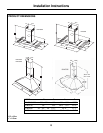
13.
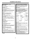
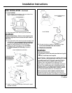
Model PVWG936:
Fix the 2 supplied brackets on the rear side of the
motor housing with 4 screws each.
Ø 3.5 x 9.5
Lower Support Bracket
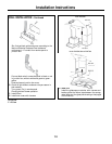
14. Hang hood with the 2 mounting hooks (screws).
WARNING
Excessive Weight Hazard - Use two or more people to move
and install range hood. Failure to do so can result in back or
other injury.
15. Hang hood with the 2 mounting hooks (screws).Level
the appliance, using a carpenters level across bottom
of hood and (models PVWS930/936 and PVWT936
only) with leveling screws in mounting hooks.
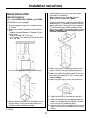
16. Secure hood with 2 screws on top and (models
PVWS930/936 and PVWT936 only) 2 screws on
bottom.
Models PVWS930/936 and PVWT936
A. Centerline on Wall
B. Mounting Hooks
C. Mounting Screws
D. Leveling Screws
Model PVWG936
Ø 6 x 80
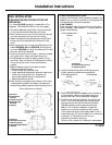
17. Install the transition at the top of the hood in case it
has been removed.
Models PVWS930/936 and
PVWT936
Ø 6 x 80
Ø 3.5 x 9.5
Model PVWG936
Ø 3.5 x 9.5
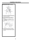
18. Connect ducting to transition. Seal with duct tape.
Do not use duct smaller than the transition.
19. Electrical connection
WARNING
• Electrical Shock Hazard
• Turn off power circuit at the service panel before wiring this
unit.
• 120 VAC, 15 or 20 Amp circuit required.
ELECTRICAL GROUNDING INSTRUCTIONS
THIS APPLIANCE IS FITTED WITH AN ELECTRICAL
JUNCTION BOX WITH 3 WIRES, ONE OF WHICH
(GREEN/YELLOW) SERVES TO GROUND THE
APPLIANCE. TO PROTECT YOU AGAINST ELECTRIC
SHOCK, THE GREEN AND YELLOW WIRE MUST BE
CONNECTED TO THE GROUNDING WIRE IN YOUR
HOME ELECTRICAL SYSTEM, AND IT MUST UNDER
NO CIRCUMSTANCES BE CUT OR REMOVED.
Failure to do so can result in death or electrical shock.
Remove the knockout and the Junction box cover and
install the conduit connector (cUL listed) in junction box.