


Installation Instructions
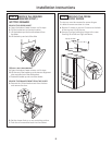
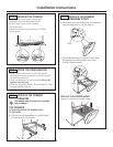
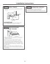
STEP 2C POSITION THE
REFRIGERATOR TO ENGAGE
THE ANTI-TIP FLOOR
AND BASE BRACKETS
A. Before pushing the refrigerator into the opening,
plug the power cord into the receptacle and
connect waterline (if equipped). Check for leaks.
B. Locate the r
efrigerator
’s RH side and mov
e back
approximately in line with the RH side of
the cabinet opening, W. This should position
the anti-tip floor brack
et to engage the anti-tip base
bracket on the refrigerator.
C. Gently r
oll the r
efrigerator back into the cabinet
opening until it comes to a complete stop.
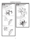
Check to see if the r
efrigerator front lines up
with the cabinet fr
ont face. If not, carefully r
ock
the refrigerator forward and backward until
engagement occur
s and you notice that
the r
efrigerator is f
ully pushed up against
the rear wall.
D
.
OPTIONAL: Adjust the r
ear (and fr
ont) wheel height
settings to fully engage the rear anti-tip brackets,
while also aligning the refrigerator front with
the cabinet fr
ont face.
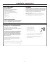
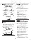
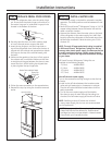
STEP 2B INSTALL ANTI-TIP BRACKET
WOOD Wall and Floor Construction:
A.
Drill the appropriate number of 1/8” pilot holes in the
center of each floor bracket hole being used (a nail
or awl may be used if a drill is not available) AND
r
emove the locator template from the floor.
B. Mount the anti-tip floor bracket by fastening the 2,
or pr
eferably 4, #10-16 hex-head screws tightly into
place as illustrated in Figure 3.
Figure 3 – Attachment to
Wall and Floor
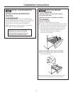
STEP 2B INSTALL ANTI-TIP BRACKET
(CONT.)
CONCRETE Wall and Floor Construction:
A. Anchors required (not provided):
4 each 1/4” x 1 1/2” lag bolts
4 each 1/2” O.D. sleeve anchors
B. Drill the recommended size holes for the anchors
into the concrete at the center of the holes marked
in Step 2.
C. Install the sleeve anchors into the drilled holes.
Place the anti-tip floor bracket as indicated
in Step 2. Remove the locator template from
the floor.
D
.
Install the lag bolts thr
ough the anti-tip floor bracket
and tighten appr
opriately.
WOOD Wall and TILE Floor Construction:
A. For this special case, locate the 2 wall holes
identified in Fig. 1. Drill an angled 1/8” pilot hole
(approx. as shown in Fig. 3) in the center
of each hole.
B. Mount the anti-tip floor bracket using the Minimum
Acceptable Installation #1, as illustrated in Fig. 2.
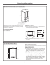
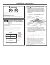
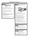
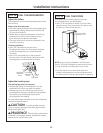
STEP 2A LOCATE ANTI-TIP FLOOR
BRACKET (CONT.)
Preferred Installation –
Wood
Preferred Installation –
Concrete
Minimum Acceptable #1 –
Wall Plate Stud
Minimum Acceptable #2–
Wood Floor
Minimum Acceptable #3–
Concrete Floor
Figure 2 – Acceptable Screw
Placement Locations
2 Screws Must
Enter Wood
or Metal Stud
Rear RH Corner
of the Refrigerator
Floor Bracket
Wall
Floor
Wall
Plate
Stud
NO
TE:
If you pull the r
efrigerator out and aw
ay fr
om
the wall for any reason, make sure the anti-tip floor
brack
et is engaged when the r
efrigerator is pushed
back against the w
all r
ear w
all.
6