


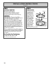
STEP 2
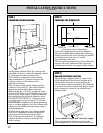
PREPARING THE COUNTERTOP
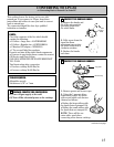
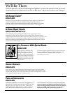
Countertop cut-out dimensions
Cut out the opening as shown in the diagram.
Measure carefully when cutting the countertop,
making sure the sides of the opening are parallel
and the front and rear cuts are exactly
perpendicular to the sides.
The front of the opening must be clear of the front
support rail on the cabinet and the rear of the
opening must clear the rear support of the cabinet.
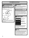
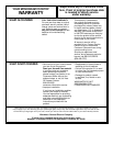
STEP 3
GAS AND ELECTRICAL LOCATION
The cooktop is equipped with a 4′ power cord,
which should reach any desired location on the
cabinet walls. However, to avoid tangling the
cord in items stored in the cabinet, it is advisable
to position the wall receptacle and the gas supply
pipe entering the cabinet in the shaded areas
marked below.
Areas suitable for gas and electricity supply
The cooktop must be disconnected from the
power supply before any servicing is carried out.
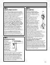
STEP 1
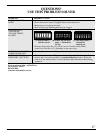
PREPARING FOR INSTALLATION
Avoid placing cabinets above the cooktop unit,
if possible, in order to reduce the hazards caused
by reaching over heated surface units.
If the cabinetry is used above the cooktop,
allow a minimum 30″ clearance between the
cooking surface and the bottom of the
unprotected cabinet.
If the clearance between the cooktop and the
cabinetry is less than 30″, the cabinet bottom
must be protected with a flame retardant
millboard at least 1/4″ thick, or gypsum board
at least 3/16″ thick, covered with 28 gauge sheet
steel or 0.020″ thick copper. Clearance between
the cooktop and the protected cabinetry must
NEVER BE LESS THAN 24″. Cabinetry above
a cooktop must not be more than 13″ in depth.
EXCEPTION: Installation of a listed microwave
oven or cooking appliance over the cooktop shall
conform to the installation instructions packed
with that appliance.
Working areas adjacent to the cooktop should
have an 18″ minimum clearance between the
countertop and the bottom of the cabinet.
If the clearance is less than 18″, the adjacent
cabinets should be at least 8″ from the side
of the cooktop.
12
INSTALLATION INSTRUCTIONS
(continued)
36″
25″
36″ min
30″
13″
18″min
8″ min
to wall
8″ min
to wall
18
5
⁄
16
″
34
7
⁄
16
″
Not less than 2
1
⁄
4
″
4
7
⁄
16
″
8
13
⁄
16
″ min.
cut-out to wall
8
13
⁄
16
″ min.
cut-out to wall
25″
19″
14″
Power receptacle
Gas inlet
4″