


10
IO-242C 05/05
4. When ducts are used, they shall be of the same cross-
sectional area as the free area of the openings to which
they connect. The minimum dimension of rectangular
air ducts shall not be less than 3 inches.
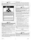
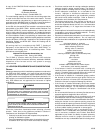
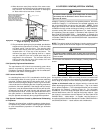
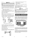
Furnace
Water
Heater
Opening
Chimney or Gas Vent
NOTE: The single opening must have
a free area of not less than one
square inch per 3000 BTU of
the total input rating of all equip-
ment in the enclosure, but not less than
the sum of the areas of all vent
connectors in the confined space.
Alternate
Opening
Location
Equipment Located in Confined Spaces; All Air from Outdoors -
Single Air Opening. See 5.3.3-b.
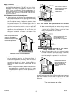
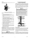
5. One permanent opening may be permitted, provided the
equipment has clearances of at least 1” from the sides
and back and 6” from the front. The opening shall
communicate directly with the outdoors and must be
located within 12” of the top of the enclosure. The
minimum free area of the opening shall be 1 square
inch per 3,000 BTU per hour of total input rating of all
equipment in the enclosure. The minimum free area
shall not be less than the sum of the areas of all vent
connectors in the confined space.
5.3.4 Specially Engineered Installations:
The requirements of 5.3.3 shall not necessarily govern when
special engineering, approved by the authority having
jurisdiction, provides an adequate supply of air for combustion,
ventilation, and dilution of flue gases.
5.3.5 Louvers and Grilles:
In calculating free area in 5.3.3, consideration shall be given
to the blocking effect of louvers, grilles or screens protecting
openings. Screens used shall not be smaller than 1/4 inch
mesh. If the area through a design of louver or grille is known,
it should be used in calculating the size of opening required to
provide the free area specified. If the design and free area is
not known, it may be assumed that wood louvers will have 20-
25 percent free area and metal louvers and grilles will have
60-75 percent free area. Louvers and grilles shall be fixed in
the open position or interlocked with the equipment so that
they are opened automatically during equipment operation.
5.3.6 Special Conditions Created by Mechanical Exhausting
or Fireplaces:
Operation of exhaust fans, ventilation systems, clothes dryers,
or fireplaces may create conditions requiring special attention
to avoid unsatisfactory operation of installed gas utilization
equipment.
VI. CATEGORY I VENTING (VERTICAL VENTING)
WARNING
T
O PREVENT POSSIBLE PERSONAL INJURY OR DEATH DUE TO ASPHYXIATION,
THIS FURNACE MUST BE
C
ATEGORY
I
VENTED.
D
O NOT VENT USING
C
ATEGORY
III
VENTING.
Category I Venting is venting at a non-positive pressure. A furnace
vented as Category I is considered a fan-assisted appliance and
the vent system does not have to be “gas tight.” NOTE: Single
stage gas furnaces with induced draft blowers draw products of
combustion through a heat exchanger allowing, in some instances,
common venting with natural draft appliances (i.e. water heaters).
All installations must be vented in accordance with National Fuel
Gas Code NFPA 54/ANSI Z223.1 - latest edition. In Canada, the
furnaces must be vented in accordance with the National Standard
of Canada, CAN/CSA B149.1 and CAN/CSA B149.2 - latest editions
and amendments.
NOTE: The vertical height of the Category I venting system must be
at least as great as the horizontal length of the venting system.
WARNING
T
O PREVENT POSSIBLE PERSONAL INJURY OR DEATH DUE TO ASPHYXIATION,
COMMON VENTING WITH OTHER MANUFACTURER'S INDUCED DRAFT APPLIANCS
IS NOT ALLOWED.
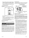
The minimum vent diameter for the Category I venting system is as
shown:
UPFLOW COUNTERFLOW
70 4 Inch 4 Inch
90 4 Inch 4 Inch
115 5 Inch 5 Inch
140 5 Inch 5 Inch
MODEL
MINIMUM VENT
Under some conditions, larger vents than those shown above may
be required or allowed. When an existing furnace is removed from
a venting system serving other appliances, the venting system may
be too large to properly vent the remaining attached appliances.
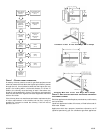
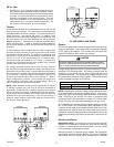
Upflow or Horizontal units are shipped with the induced draft
blower discharging from the top of the furnace. (“Top” is as viewed
for an upflow installation.) The induced draft blower can be rotated
90 degrees for Category I venting (Figure 3). For horizontal
installations, a four inch single wall pipe can be used to extend the
induced draft blower outlet 1/2” beyond the furnace cabinet. Vent
the furnace in accordance with the National Fuel Gas Code NFPA
54/ANSI Z223.1 - latest edition. In Canada, vent the furnace in
accordance with the National Standard of Canada, CAN/CSA B149.1
and CAN/CSA B149.2 - latest editions and amendments.