


11
IO-242C 05/05
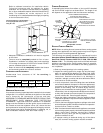
Venting
THIS FURNACE IS NOT DESIGN CERTIFIED TO BE
HORIZONTALLY VENTED.
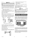
Supply
Air
Upflow Rotated Induced Draft Blower
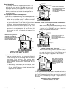
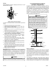
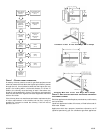
To rotate the induced draft blwer counterclockwise, proceed as
follows:
1. Disconnect electrical power from the furnace.
2. Disconnect the induced draft blower power leads, flue
pipe, and pressure switch tubing.
3. Remove the round cutout from the appropriate side of the
furnace.
4. Remove and save the four screws that hold the induced
draft blower to the flue collector box.
5. Turn the induced draft blower 90 degrees clockwise, or
counterclockwise. The gasket is adhered to the back
plate and will rotate with the blower assembly.
6. Reinstall the induced draft blower on the flue collector
box, using the four screws removed in Step 3. Tighten
screws to provide an airtight seal.
7. Reconnect the induced draft blower power leads. NOTE:
If the wires are not long enough, pull extra wire from the
wire bundle in the blower compartment.
8. Remove and save the screw that holds the pressure
switch to the furnace top panel.
9. Relocate the pressure switch to the same side as the
flue outlet in the hole provided.
10. Reconnect the draft blower power leads, flue pipe, and
pressure switch tubing. Make sure that all wires and the
pressure switch tubing are at least one inch from the flue
pipe, or any other hot surfaces.
11. Restore power to the furnace.
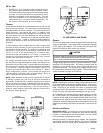
Counterflow units are shipped with the induced draft blower
discharging from the top of the furnace. (“Top” as viewed for a
counterflow installation.) Vent the furnace in accordance with
the National Fuel Gas Code NFPA 54/ANSI Z223.1 - latest edition.
In Canada, vent the furnace in accordance with the National
Standard of Canada, CAN/CSA B149.1 AND CAN/CSA B149.2 -
latest editions and amendments.
WARNING
NEVER ALLOW THE PRODUCTS OF COMBUSTION, INCLUDING CARBON
MONOXIDE, TO ENTER THE RETURN DUCTWORK OR CIRCULATION AIR SUPPLY.
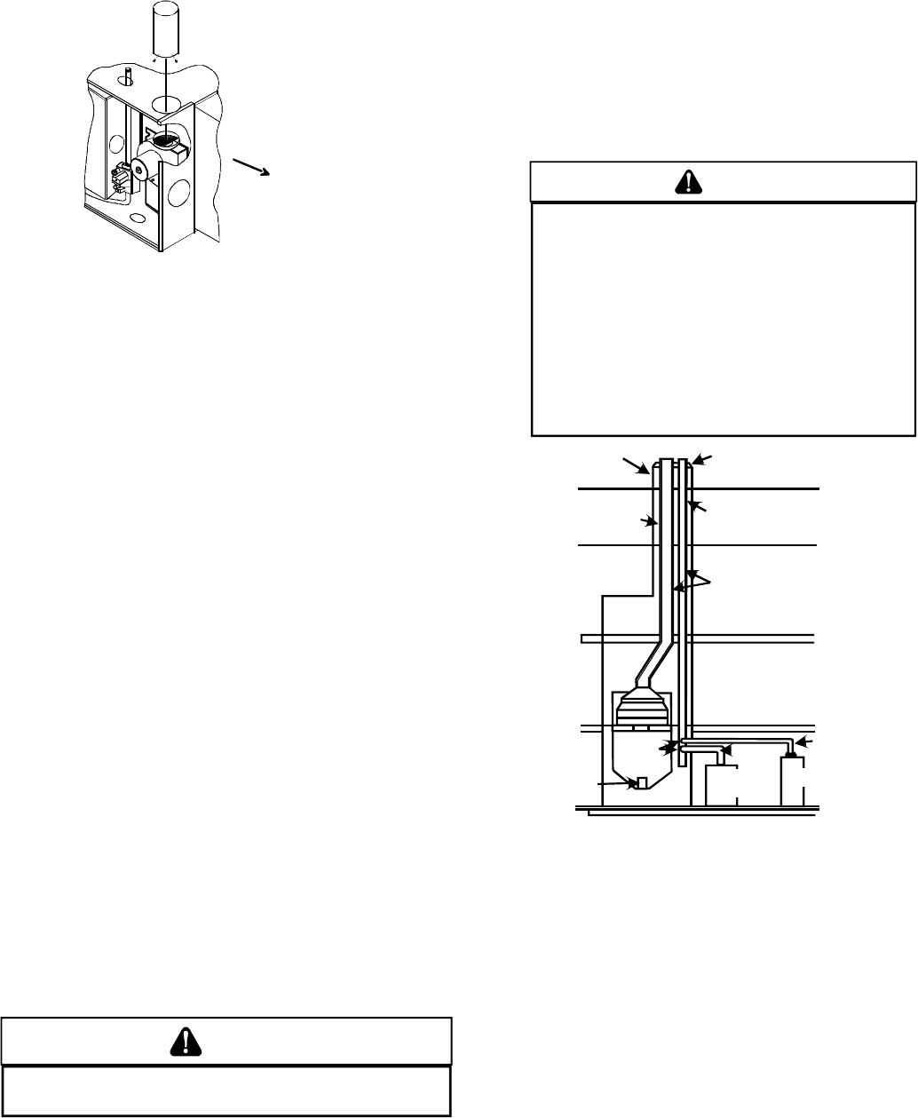
VII. EXTERIOR MASONRY CHIMNEYS -
CATEGORY I FURNACES ONLY
An exterior masonry chimney is defined as a “Masonry chimney
exposed to the outdoors on one or more sides below the roof
line.” The ability to use a clay lined masonry chimney depends
on a parameter not associated with interior chimneys. This
variable is the geographic location of the installation.
Researchers have discovered that the winter design
temperatures have a direct impact on the suitability of this type of
venting. In most situations, the existing masonry chimneys will
require a properly sized metallic liner.
WARNING
P
OSSIBILITY OF PROPERTY DAMAGE, PERSONAL INJURY OR DEATH
DAMAGING CONDENSATION CAN OCCUR INSIDE MASONRY CHIMNEYS WHEN A
SINGLE FAN ASSISTED
C
ATEGORY
I
APPLIANCE (80%
AFUE
FURNACE) IS
VENTED WITHOUT ADEQUATE DILUTION AIR.
D
O NOT CONNECT AN 80%
FURNACE TO A MASONRY CHIMNEY UNLESS THE FURNACE IS COMMON VENTED
WITH A DRAFT HOOD EQUIPPED APPLIANCE OR THE CHIMNEY IS LINED WITH A
METAL LINER OR
TYPE B METAL VENT. ALL INSTALLATIONS USING MASONRY
CHIMNEYS MUST BE SIZED IN ACCORDANCE WITH THE APPROPRIATE VENTING
TABLES.
I
F AN 80% FURNACE IS COMMON VENTED WITH A DRAFT HOOD
EQUIPPED APPLIANCE, THE POTENTIAL FOR CONDENSATION DAMAGE MAY
STILL EXIST WITH EXTREMELY COLD CONDITIONS, LONG VENT CONNECTORS,
EXTERIOR CHIMNEYS, OR ANY COMBINATION OF THESE CONDITIONS.
T
HE
RISK OF CONDENSATION DAMAGE IS BEST AVOIDED BY USING THE MASONRY
CHIMNEY AS A PATHWAY FOR PROPERLY SIZED METAL LINER OR
T
YPE
B
METAL VENT.
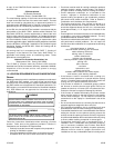
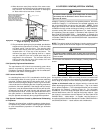
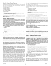
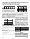
Wash
Crown
Clay Tile Size: 8" x 8" x12"
(Each x 24" Length)
Clay Tile Size Generally
12" x 12" (24" Length)
1/2" to 1" Air Space
Second Floor
First Floor
Attic Floor
Roof Line
Throat
Damper
Breech
Clean Out
Fan Assisted
Forced Air
Furnace
Natural Draft
Water Heater
Water Heater
Vent Connector
Basement Floor
F.A.F. Vent
Connector
Typical Multiple Flue Clay Tile Chimney
CHECKLIST SUMMARY
This checklist serves as a summary of the items to be checked
before venting an 80+ furnace into a masonry chimney. In addition,
we recommend that a qualified serviceman use this checklist to
perform a yearly inspection of the furnace venting system.
This checklist is only a summary. For detailed information on
each of the procedures mentioned, see the paragraph referenced
with each item.
This inspection is based upon a draft topical report, “Masonry
Chimney Inspection and Relining”, issued by the Gas Research
Institute. While not yet finalized, we believe this report represents
the best information on this subject which is currently available.