


30
IO-242C 05/05
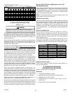
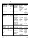
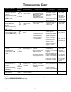
TROUBLESHOOTING CHART
Fault Description(s)
Symptoms of Abnormal
Operation
4
4 FLASHES
Associated
LED Code
2
• Circulator blower runs
continuously. No furnace
operation.
• Integrated control module
diagnostic LED is flashing
FOUR (4) flashes.
6
6 FLASHES
7
7 FLASHES
• Furnace fails to operate.
• Integrated control module
diagnostic LED is flashing
SIX (6) flashes.
• Normal furnace
operation.
• Integrated control
module diagnostic LED
is flashing SEVEN (7)
flashes.
• Rollout limit
open.
• Flame sense
microamp signal is
low.
• Insufficient conditioned air
over the heat exchanger.
Blocked filters, restrictive
ductwork, improper
circulator blower speed,
or failed circulator blower.
Possible Causes Corrective Action Cautions and Notes
• Check filters and
ductwork for blockage.
Clean filters or remove
obstruction.
• Check circulator blower
speed and performance.
Correct speed or replace
blower if necessary.
• Turn power OFF
prior to repair.
• See Product
Data Bulletin for
allowable rise
range and proper
circulator speed.
• Flame sensor is coated/
oxidized.
• Flame sensor incorrectly
positioned in burner
flame.
• Lazy burner flame due to
improper gas pressure or
combustion air.
• Sand flame sensor is
coated/oxidized.
• Inspect for proper sensor
alignment.
• Check inlet air piping for
blockage, proper length,
elbows, and termination.
• Compare current gas
pressure to rating plate
info. Adjust as needed.
• Turn power OFF
prior to repair.
• Clean flame
sensor with steel
wool.
• See “Vent/Flue
Pipe” section for
piping details.
• See rating plate
for proper gas
pressure.
•See “Vent/Flue
Pipe” section for
piping details.
•Replace induced
draft blower with
proper
replacement part.
•Primary limit
circuit is open.
• Induced draft blower runs
continuously. No furnace
operation.
• Integrated control module
diagnostic LED is flashing
continuously.
C
CONTINUOUS
FLASHING
• Polarity of 115
volt power is
reversed.
• Polarity of 115 volt AC
power to furnace or
integrated control module
is reversed.
• Poor unit ground.
• Review wiring diagram to
correct polarity.
• Verify proper ground.
Correct if necessary.
• Check and correct wiring.
• Turn power OFF
prior to repair.
2
LED Flash code will cease if power to the control module is interrupted through the disconnect or door switch.
3
Applies to GMS8/GDS8/GHS8 Models only.
• Normal operation.
• LED is steady on
steady on
• Check burners for
proper alignment.
• Check flue and air inlet
piping for blockage,
proper length, elbows,
and termination.
Correct as necessary.
• Check induced draft
blower for proper
performance.
Replace, if necessary.
• Tighten or correct
wiring connection.
• Flame rollout.
• Misaligned burners,
blocked flue and/or air
inlet pipe, or failed
induced draft blower.
• Loose or improperly
connected wiring.
• Induced draft blower and
circulator blower runs
continuously. No furnace
operation.
• Integrated control module
diagnostic LED is flashing
FIVE (5) flashes.
5
5 FLASHES
•Flame sensed
with no call for
heat.
• Short to ground in flame
sense circuit.
• Correct short at flame
sensor or in flame
sensor wiring
• Turn power OFF
prior to repair.