


Grind’n Brew® Coffee Systems Page 11
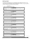
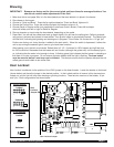
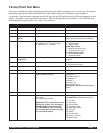
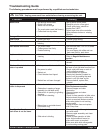
Factory/Field Test Menu
This menu is intended to check product functionality both at the end of the factory line and in the field. This mode is
entered by pressing and holding the DOWN key on the display board and Full/Half key on the keypad for
10 seconds. Once the menu is entered, the unit will start with an LED test that lights all LEDs and segments on the
display. Navigation is done just like the User Menu. Refer to the table below for operation. Field Test Mode exits
after stepping through all modes only – there is not a timeout.
Step Function Operation Description
1 LED Test All LEDs ON Verify that all LEDs turn on.
2 Firmware Version Display firmware version Shows the software version of the control.
3 Date Code Display date code/serial ID Not used with Grind’n Brew®
4 Non Resetable Bean
Counter
Scroll non-resetable bean counter Shows the total number of seconds the
grinder has been grinding (non-resetable)
5 Configuration Inputs Each digit of the display corresponds to a
configuration input. The input is either
“0” - disabled or “1” - enabled.
Highest Digit (left most):
“1” - Double Hopper;
“0” - Single Hopper
Middle Digit (center):
“1” - Always show bean count;
“0” - Don’t show bean count
Lowest Digit (right most):
“1” - Grind’n Brew® Model;
“0” - Grind Only Model
6 Display Water
Temperature
Show averaged A/D reading of temperature Show the current temperature in °F of the
thermistor
7 Display Water Level 1 Show averaged A/D reading of water level 1 If > 500 water level full,
If < 500 water level not full
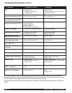
8 Display Water Level 2 Show averaged A/D reading of water level 2 Not used with Grind’n Brew®
9 Show Input Display scrolls “InPut” Input Test Mode
10 Input Test Press each key and the display will show a
number related to that key
Hopper Button: 12
Size Button: 10
Grind/Brew Button: 8
Down Button: 0
Up Button: 2
Start Switch: 16
Basket Out Switch: 17
Select Button: advances Factory Test to
Step 11
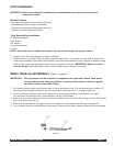
11 Show Output Display scrolls “outPut” Output Test Mode
12 Output Test Turns on each relay separately. Displays
“O##“ where:
## = 2 digit output number
IMPORTANT: Each output will be turned
ON when its number is on the display
REGARDLESS of temperature or fill
level. Be CAREFUL not to overfill the
tank and keep electric items out of the
way of the brew channel.
Scroll through relay outputs with the UP
and DOWN keys. Outputs are as follows:
O01: Fill Valve
O02: Brew Valve
O03: Grind Shutter
O04: Left Auger Motor
O05: Right Auger Motor
O06: not used
O07: Heater
O08: Grinder Motor
O09: Basket Out Light
O10: Ready Light