


Grind’n Brew® Coffee Systems Page 7
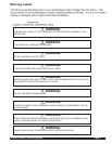
Brewing
IMPORTANT: Brewers are factory set for the correct grind and brew times for average situations. You
should not need to make adjustments in the field.
1. Make sure that a new paper filter is in the brew basket and the brew basket is in place in the brewer.
2. Place beans in the hopper.
3. Choose to “Grind and Brew”. Press the far right touchpad so “Grind and Brew” lights are lit.
4. Choose the Portion Size. Press the middle touchpad until desired volume is lit.
5. Choose Decaf or Regular coffee (only applicable to dual bean Grind’n Brews). Press left touchpad.
Arrow will either point left or right for Decaf or Regular.
6. Place a decanter or airpot under the brew basket, depending on the model.
7. Press Start. You will see the coffee bean level go down slightly. You will hear the coffee grind. Coffee is automati-
cally ground, portioned and placed in brew basket. Then ground coffee is automatically brewed. The Ready light
will now blink, indicating that grinding and brewing are in progress. This will take 3-4 minutes for a 1/2 gal. pot.
Portions are factory set. A stop function is added to the start switch. When this switch is depressed, it allows the
unit to stop during the selected grind, brew or grind and brew functions.
After brewing a pot, the tank must reheat. Reheat time is 5 1/2 - 8 minutes for 120V brewers and half that time
for 230V machines. Remember that the brewer will not function (although the grinder will) until the Ready light is
on, indicating that the water is hot enough to brew. A flashing green light indicates that the brewer is reheating or
that there is a cycle in progress. Do not remove the brew basket while the light is flashing. The brew basket
must be removed before a new brew can be initiated. This feature ensures that the operator discards the old
coffee grounds and installs a new coffee filter.
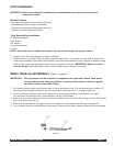
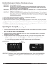
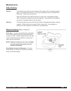
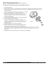
User Lockout
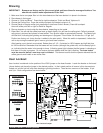
User Lockout is achieved via the position of the LOCK jumper on the board header. Locate the header on the board
(shown below) and place the jumper in the desired position. In the Locked position all menus in this document are
locked out, and the unit will only allow brewing or grinding functions. There are two versions of the header, 10 pin
and 2 pin. Both configurations are shown below.
User Lockout Jumper
User
Lockout
Jumper
Locked
Unlocked
LOCK
LOCK
2 Pin Version
1 LOCK
1 LOCK
Locked
Unlocked
10 Pin Version