


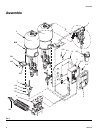
Assemble
309521J 13
Cart-mounted
1. Secure metering valve assembly (6) to cart/stand
with screws (913), washer (914), and nuts (915).
F
IG. 1, page 8.
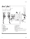
2. Connect fluid lines (provided by installer) between
pumps and metering valves.
3. Cut air line tubing (included) to length needed to
connect between metering valves (601) and sole-
noid outlets. F
IG. 3, page 10, and FIG. 6.
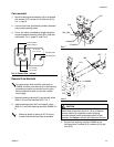
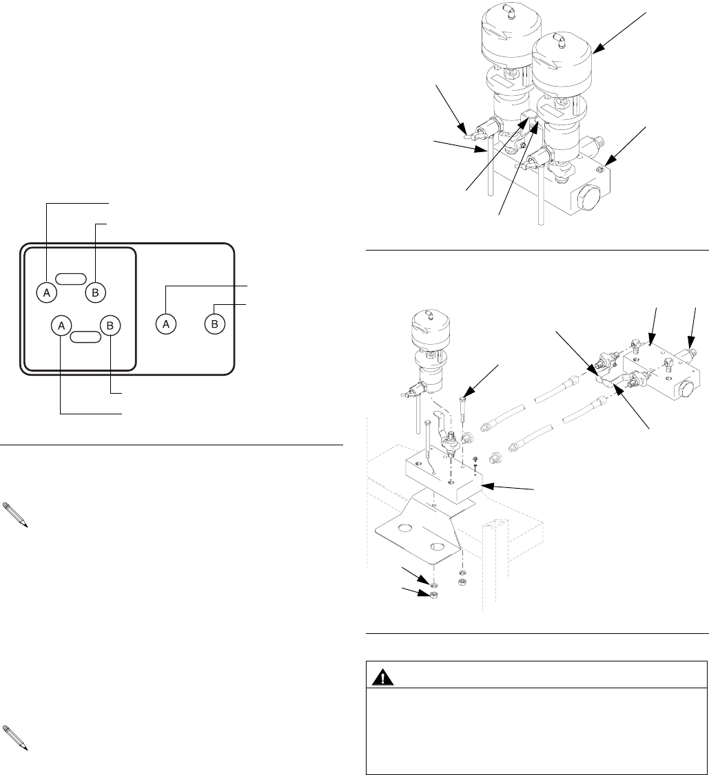
Remote Fluid Manifold
1. Remove metering valves (601) and shutoff valves
(606, 611) from fluid manifold (607). F
IG. 7.
2. Install metering valves (601) and shutoff valves
(606, 611) onto fluid metering manifold 15A898. F
IG.
8.
3. Secure fluid metering manifold 15A898 on the
cart/stand with 2 screws (913), washers (914) and
nuts (915).
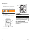
F
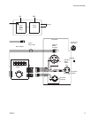
IG. 6: Control Box - bottom
To install remote fluid manifold, order part no.
15A898. All other parts referred to in the following
procedure are parts you remove from the stan-
dard manifold and reuse or parts the installer
must supply.
• Maximum length of tubing is 36” (914 mm).
Locate fluid manifold as close as possible.
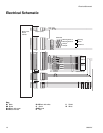
OPEN
CLOSE
DOSING VALVES AIR MOTOR
PILOT VALVES
Top of Valve B
Top of Valve A
Bottom of Valve A
Bottom of Valve B
Pilot Valve A side
Pilot Valve B side
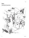
FIG. 7
F
IG. 8
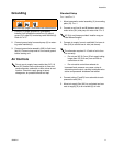
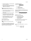
CAUTION
Do not assemble static mixer directly to fluid manifold.
Install static mixer after first 50 ft. (15 m) of hose to
ensure material is completely mixed. Spraying
unmixed material could necessitate rework of part
sprayed. See Setup in Xtreme Mix Operation manual.
601
607
A side 606
B side 611
918
919, 920
15A898
607
606
611
E
913
914
915