


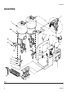

Assemble
14 309521J
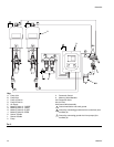
4. Screw ball valves (606, 611 - purchased separately)
into fluid mix manifold (607).
5. Select appropriate fittings and fluid hose sizes and
lengths to connect between fluid metering manifold
15A898 and mix manifold (607).
6. Connect fluid lines (provided by installer) between
pumps and metering valves (601).
7. Connect mixed material hose to fluid mix manifold
(607) outlet (E).
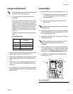
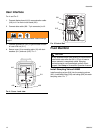
8. Cut air line tubing (included) to length needed to
connect between metering valves (601) and sole-
noid outlets. F
IG. 3, page 10, and FIG. 6, page 13.
9. Cut air line tubing, included, (F, G, H, J - F
IG. 3,
page 10) to length needed to connect between
metering valves (601) and solenoid outlets.
10. Connect ground wires.
Balancing Back Pressure
Flow rates and/or viscosity differences between compo-
nent materials can create different pressure drops from
the proportioner to the manifold, causing unequal back
pressure. This will effect mix ratio accuracy.
To calculate pressure loss:
Pressure Loss = 0.000273 x Q x V L
D
4
Q= Flow (GPM)
V = Viscosity in centipoise
L = Length of pipe in feet
D
4
= Pipe diameter to the 4th power
Example: If you need to pump 1 gpm of high solids paint
(40 seconds in a Zahn #2 cup = 100 cp) 100 ft. in a sys-
tem using 1/4” pipe:
Pressure Loss = 0.000273 x 1 gpm x 100 cp x 100 ft.
(.364 ID) .018 D
4
factor
Pressure Loss = 152 psi
Reduce pressure loss by using:
• Large diameter pipe or tubing
• Constant tubing or pipe size
• Long runs without bends
• Long radius elbows
You can balance differences in component back pres-
sure by adjusting hose diameter and length.
D
4
= .018 for 1/4” pipe
.06 for 3/8” pipe
.15 for 1/2” pipe
Using the previous example (.000273 x 1 x 100 x 100 =
2.73):
Pressure drop: 1/4” pipe = 152 psi
3/8” pipe = 46 psi
1/2” pipe = 18 psi
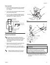
Balance pressure drops in the 2 lines as
instructed below to assure an accurate mix ratio.
This procedure is for the remote fluid manifold
only.