


– 11 –
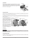
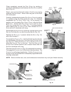
To Reinstall the Knife . . .
• Orient the RIDGE on the KNIFE HUB so it points to the PIN on
the RING GUARD at the 1 o'clock position (Fig. 24).
• Place the K
NIFE and TOOL so the PIN on the KNIFE REMOVAL
TOOL is at the 11 o'clock position (Fig. 23). The SLOTS on
the KNIFE REMOVAL TOOL fit around the three PINS on the
R
ING GUARD (FIG. 20).
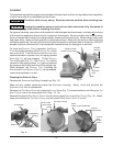
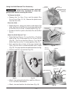
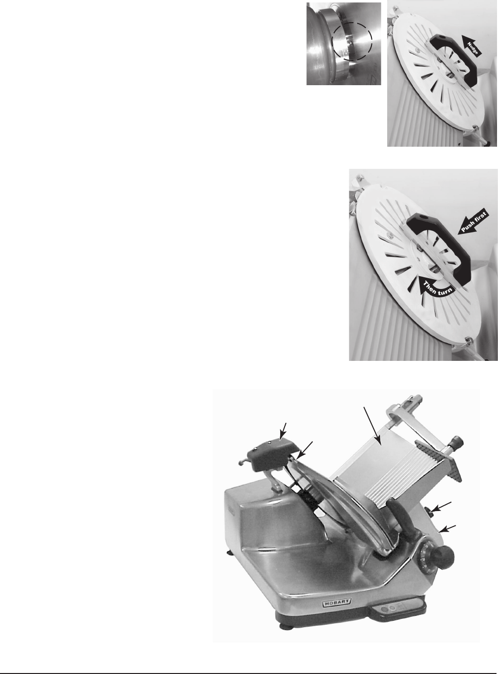
• If the T
OOL does not push the pins on the back of the KNIFE
into the HUB (Fig. 25), slightly nudge the HANDLE upwards
(Fig. 26) to lock the pins into the K
NIFE NUT.
• First, push the H
ANDLE firmly, all the way into the HUB to engage
the pins. Then, turn the H
ANDLE clockwise until it stops (Fig. 27).
You may experience resistance when turning.
• The K
NIFE is reattached. Lift the TOOL up and out.
• Replace the plastic cover on the K
NIFE NUT.
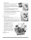
Reassemble Slicer Parts
• Place the plastic R
ING GUARD COVER on the RING GUARD, align
using the three guide P
INS (Fig. 14).
• Place the T
OP KNIFE COVER on top of the RING GUARD COVER,
aligning with the three guide P
INS (Fig. 13). Secure the RING
GUARD COVER and the TOP KNIFE COVER by turning the LATCH KNOB
(Fig. 7) counterclockwise while lowering the TOP KNIFE COVER;
then, release the L
ATCH KNOB and turn it clockwise until snug.
• Lower the S
HARPENER so the ROD AND
PIN, underneath, fit the SLOT in the
S
HARPENER MOUNT (Fig. 12).
• Reinstall the P
RODUCT TRAY by holding
it with both hands and lowering the
bottom of the S
UPPORT ARM so it fits on
the C
ARRIAGE HINGE PINS (Fig. 17).
• Return the P
RODUCT TRAY to the GAUGE
PLATE by tilting it to the left. Turn the
K
NOB on the SUPPORT ARM loosely in
either direction until it moves inward,
then turn it clockwise until snug
(Fig. 28).
To reattach accessories —
refer to page 3.
SHARPENER
KNIFE COVER
KNOB
PRODUCT TRAY
SUPPORT
ARM
Fig. 28
Fig. 26
Fig. 25
Fig. 27