


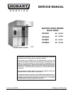

OV500 SERIES RACK OVEN
TABLE OF CONTENTS
GENERAL ................................................................................ 3
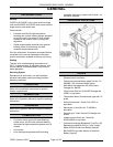
Introduction ............................................................................ 3
Location .............................................................................. 3
Operation ............................................................................. 3
Cleaning .............................................................................. 3
Lubrication ............................................................................ 3
Control Location ........................................................................ 4
Tools................................................................................. 4
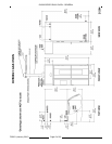
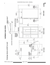
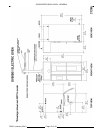
OV500G1 Gas Oven Specifications ......................................................... 5
OV500G2 Gas Oven Specifications ......................................................... 7
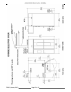
OV500E1 Electric Oven Specifications ...................................................... 9
OV500E2 Electric Oven Specifications ..................................................... 11
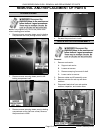
REMOVAL AND REPLACEMENT OF PARTS ................................................... 13
Steam Panel .......................................................................... 13
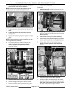
Rack Rotator Assembly ................................................................. 13
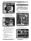
Rotator Motor ......................................................................... 15
Actuator ............................................................................. 16
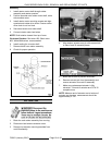
Convection Blower/motor ................................................................ 17
Gas Valve ............................................................................ 18
Gas Manifold / Orifices .................................................................. 18
Heat Exchanger ....................................................................... 19
Ignition Module ........................................................................ 21
Controller ............................................................................ 21
High Limit Switch ...................................................................... 22
Draft Inducer Motor ..................................................................... 23
Pressure Switches ..................................................................... 24
Oven Cavity Vent Motor ................................................................. 24
Oven Cavity Vent Switch ................................................................ 25
Thermostat (Back Up System Only) ........................................................ 25
Temperature Probe .................................................................... 26
Eprom Replacement.................................................................... 27
Door Swing Change .................................................................... 27
SERVICE PROCEDURES AND ADJUSTMENTS................................................. 28
Controller Input/output Status Diagnostic .................................................... 28
Ignition Module Self Diagnostics .......................................................... 29
Temperature Probe Test ................................................................ 29
Controller Temperature Calibration ........................................................ 29
Controller Settings ..................................................................... 29
Burner Adjustments .................................................................... 34
Flame Sense Location .................................................................. 38
Flame Sense Current Test ............................................................... 38
Combustion Analysis ................................................................... 38
F25361 (January 2010)
Page 2 of 60