


42
B. Removal and Replacement of Refrigeration System Cartridge
CAUTION
The refrigeration system cartridge should not be removed until the refrigerant
has been properly recovered or the refrigeration system has been properly
pumped down. For refrigeration system repairs, the refrigerant recovery
proceduremustbeused.See"IV.B.1.RefrigerantRecoveryProcedure."For
non‑refrigerationsystemrepairs,see"IV.B.2.Pump‑DownProcedure."Donot
discharge the refrigerant into the atmosphere.
1. Refrigerant Recovery Procedure
1)Removethefrontpanel.Movethepowerswitchtothe"OFF"position,thenunplugthe
unit.
2) Remove the left side panel.
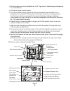
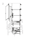
3) Connect the gauge manifold hoses to the receiver service valve (high-side) and the
compressor access valve (low-side). See Fig. 1.
4) Run in the receiver service valve stem a couple of turns for high-side system access.
Note: Be sure the high-side gauge manifold hose is on the receiver service valve
before opening the receiver service valve.
5) Using proper refrigerant practices, recover the refrigerant and store it in an approved
container. Do not discharge the refrigerant into the atmosphere.
6) When the recovery is nished, close the gauge manifold valves and back out the
receiver service valve stem all the way and tighten.
Note: Be sure the receiver service valve stem is backseated all the way out and tight.
7) Close the rail high and low-side service valves. Run in the rail service valve stems all
the way until tight.
Note: Be sure the rail high and low-side service valve stems are seated all the way in
and tight.
8) Disconnect the rail refrigerant tubes from the rail service valves. Use a backup wrench
when loosening the ttings. See Fig. 1.
9) Remove the screw securing the rail service valve bracket.
10) Disconnect the power supply cord connector, rail thermistor connector, and the
perimeter heater/rail fan motor connector.
11) Remove the wire cover below the control box.
12) Remove the upper and lower attachment nuts and washers from the control box and
the hex head bolt from the base of the refrigeration cartridge. See Fig. 1.