


49
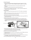
8) Braze the ttings while purging with nitrogen gas owing at a pressure of 3 to 4 PSIG.
9) Replace the removed evaporator parts in their correct positions.
10)Oncetherepairiscomplete,returntostep15in"IV.B.1.RecoveryProcedure"for
refrigeration system cartridge replacement.
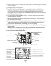
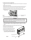
E. Removal and Replacement of Expansion Valve
Moisture in the refrigeration circuit may exceed drier capacity and freeze up at the
expansion valve.
CAUTION
1. Always install a new drier every time the sealed refrigeration system is
opened.
2. Do not replace the drier until after all other repair or replacement has been
made. Install the new drier with the arrow on the drier in the direction of the
refrigerant ow.
3. When brazing, protect the valve body and drier by using wet cloths to
prevent the valve body and drier from overheating. Do not allow the valve
body or drier to exceed 250°F (121°C).
1)Movethepowerswitchtothe"OFF"position,thenunplugtheunit.
2) Remove the panels.
3) Recover the refrigerant and store it in an approved container.
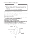
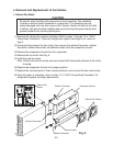
4) Remove the insulation and the expansion valve bulb on the suction line.
5) Remove the expansion valve cover and disconnect the expansion valve. Place the new
expansion valve in position.
6) Remove the drier, then place the new drier in position.
7) Braze all ttings while purging with nitrogen gas owing at a pressure of 3 to 4 PSIG.
8) Use an electronic leak detector or soap bubbles to check for leaks. Add a trace of
refrigerant to the system (if using an electronic leak detector), and then raise the
pressure using nitrogen gas (140 PSIG). DO NOT use R-404A as a mixture with
pressurized air for leak testing.
9) Evacuate the system and charge it with refrigerant; see the nameplate for the required
refrigerant charge.
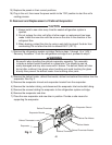
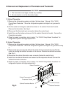
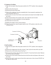
10) Attach the expansion valve bulb to the suction line in the same location as the previous
bulb. The bulb should be between the 10 and 2 o'clock position on the tube. Be sure to
secure the bulb with the clamp and holder and to insulate it.
11) Place the expansion valve cover in position.
12) Replace the panels in their correct positions.
13)Plugintheunit,thenmovethepowerswitchtothe"ON"positiontostarttheunit's
cooling process.