


58
IV. Service Diagnosis
WARNING
1. This unit should be diagnosed and repaired only by qualied service
personnel to reduce the risk of death, electric shock, serious injury, or re.
. Risk of electric shock. Use extreme caution and exercise safe electrical
practices.
3. Moving parts (e.g., fan blade) can crush and cut. Keep hands clear.
4. CHOKING HAZARD: Ensure all components, fasteners, and thumbscrews
are securely in place after the unit is serviced. Make sure that none have
fallen into the dispenser unit/storage bin.
5. Make sure all food zones in the icemaker and dispenser unit/storage bin are
clean after the unit is serviced. For cleaning procedures, see "VI. Cleaning
and Maintenance."
A. Ice Production Check
To check production, prepare a bucket or pan to catch the ice and a set of scales to
weigh the ice. After the icemaker has operated for 10 to 0 minutes, catch the ice
production for 10 minutes. Weigh the ice to establish the batch weight. Multiply the batch
weight by 144 for the total production in 4 hours.
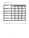
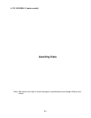
B. Diagnostic Procedure
This diagnostic procedure is a sequence check that allows you to diagnose the electrical
system and components. Before proceeding, check for correct installation, adequate
water supply (minimum of 10 PSIG, maximum of 113 PSIG) and proper voltage per
unit nameplate. Check that the 4VAC 1A fuse and the 115VAC 3A GM fuse are good.
When checking for high-voltage (115VAC), always choose a white (W) neutral wire
to establish a good neutral connection. When checking for low-voltage (secondary)
(4VAC), always choose a light blue (LBU) neutral wire to establish a good neutral
connection. If the icemaker is in alarm, see "II.C.3. Alarm Safeties."
Note: FM/FMR and EHH (-C model only) energize when "GM" LED turns on. On MLH
model, CB X1 Comp relay energizes LLV and SLV.
1) Turn off the power supply.
) Remove the front panel, then move the power switch to the "OFF" position.
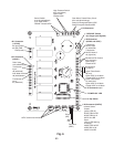
3) Remove the control box cover and access CB.
4) Check the S1 dip switch settings, see "II.C.4.a) Default Dip Switch Settings" to assure
that they are in the correct positions. For proper operation of IS, conrm that S1 dip
switch 7 is in the "ON" position.
WARNING
1. Risk of electric shock. Use extreme caution and exercise safe electrical
practices.
. Moving parts (e.g., fan blade) can crush and cut. Keep hands clear.