


6
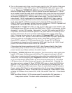
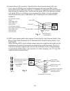
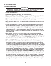
4) Infrared Sensor (K6 connector): Check that the infrared sensor green LED is on.
If not, check for 0VDC from the black K6 connector dark blue wire (DBU) to the
K6 connector brown (BR) wire. See Fig. 4. If 0VDC is not present, the control board is
bad and must be replaced. Next, conrm that the yellow LED is not ashing or steady.
If IS yellow LED is on or ashing, move ice away from IS lens. If no ice is present,
clean the lens with a warm, clean damp cloth. If cleaning the lens does not work,
replace IS.
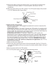
Red positive test lead to white
K5 connector pin closest to
red K4 connecotor
Fig. 5
Control Board K9 Connector
Red Positive
Test Lead
Black Negative
Test Lead
Multimeter
Fig. 4
Red Positive
Test Lead
Black Negative
Test Lead
0VDC
Multimeter
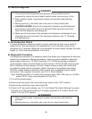
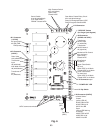
5) 5VDC control board switch output checks: Control Switch, High Pressure Switch, Gear
Motor Protect Relay (terminals 3 & 5), Mechanical Bin Control Proximity Switch, and
Float Switch.
When checking 5VDC control voltage, always place the red positive test lead from the
multimeter to the white K5 connector pin closest to the red K4 connector. See Fig. 5.
Then place the black negative test lead from the multimeter to the corresponding pin
to complete the 5VDC check. If the icemaker is in alarm (beeping), see "II.C..g) LED
Lights and Alarm Safeties Chart."
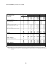
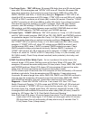
Infrared Sensor (0VDC)
Open (yellow LED ashing or steady)
0VDC DBU to BR
0VDC DBU to W
0VDC W to BR
Infrared Sensor (0VDC)
Closed
0VDC DBU to BR
0VDC DBU to W
0VDC W to BR
Brown (BR)
Dark Blue (DBU)
White (W)
• K6 Connector
Infrared Sensor
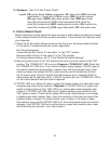
5VDC
Control Switch
white/black (W/BK)
High-Pressure Switch
yellow (Y) wires
Gear Motor Protect Relay
(terminals #3 and #5)
white/orange (W/O)