


59
5) Turn on the power supply, then move the power switch to the "ON" position. Make sure
the control switch is in the "ICE" position. CB "POWER OK" LED and IS green LED
turn on. Diagnosis "POWER OK" LED: Check that CB "POWER OK" LED is on. If not,
check for proper supply voltage (115VAC) input to the control transformer. If 115VAC
is not present, check the power switch and breaker. Next, check that the circuit protect
relay is de-energized (closed between terminals #1 and #5). If the circuit protect relay
is energized (08/30VAC), conrm proper power supply. The circuit protect relay
helps protect 115VAC components from exposure to 08/30VAC. Next, check for
proper outpout voltage (4VAC) from the control transformer. If "POWER OK" LED
is off, check 4VAC at CB K8 connector pin #1 white/red (W/R) to pin # light blue
(LBU). If 4VAC is not present, replace the control transformer. If 4VAC is present and
"POWER OK" LED is off, CB is bad and must be replaced.
Diagnosis IS: If "POWER OK" LED is on and IS green LED is off, check 0VDC at CB
K6 connector brown (BR) wire to dark blue (DBU) wire. If 0VDC is not present, conrm
dip switch 7 is in the "ON" position. If dip switch 7 is in the "ON" position and 0VDC is
not present, CB is bad and must be replaced. If IS yellow LED is on or ashing, move
ice away from IS lens. If no ice is present, clean the lens with a warm, clean damp
cloth. If cleaning the lens does not work, replace IS. Diagnosis MBC: Conrm S1 dip
switch 7 is in the "OFF" position. Check that the actuator paddle is properly positioned.
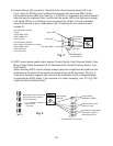
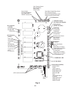
Check for continuity across MBC proximity switch. When MBC proximity switch is
closed 5VDC is present at CB K8 connector pin #3 or #4 gray (GY) to CB white
K5 connector pin closest to red K4 connector (5VDC gnd). See Fig. 6. If 5VDC is not
present, the control board is bad and must be replaced.
CB monitors the following switches with 5VDC: High-Pressure Switch, Gear Motor
Protect Relay (relay terminals 3 & 5), and Mechanical Bin Control. When 5VDC is
present across any of these switches, the switch is open.
6) Fill Cycle – "WTRIN" LED is on. WV energizes. The 90-second low water safety timer
begins. LF/S closes. Nothing occurs at this time. The reservoir continues to ll until
UF/S closes, terminating the 90-second low water safety timer, starting the 30-minute
freeze timer, and de-energizing WV. Diagnosis: Check that "WTRIN" LED turns
on. If not, make sure IS yellow LED is off. If not, move ice away from IS. If IS yellow
LED does not turn off, clean the lens with a warm, clean damp cloth. If cleaning the
lens does not work, replace IS. When "WTRIN" LED turns on, check that WV lls the
reservoir. If not, check 4VAC to WV from CB K connector pin #8 white/brown (W/
BR) wire to a light blue (LBU) neutral wire. Check for continuity through WV solenoid.
If open, replace WV. Check for water supply line shut-off valve closed, clogged water
lters, and clogged WV screen. Check that DV is not leaking by. Check that WV shuts
off when UF/S closes. If not, check UF/S, LF/S, CB, and WV. See "IV.E.1. Float Switch
Check."
Note: Low Water Safety–If UF/S remains open 90 seconds after WV energizes, a
1-beep alarm sounds. This alarm resets automatically once UF/S closes.