


Step 2: Connect to gas supply
1. The inlet to the appliance is ISO 7
- Rp
1
⁄
2
” internal thread situated
towards the top right hand rear
corner.
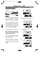
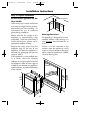
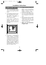
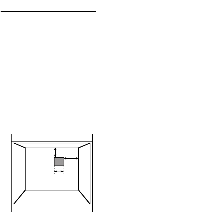
2. Fit the bayonet connection to the
wall in the shaded area as shown.
The shaded area shown is
applicable to installations in
minimum depth cabinets.
If more room is available, the
bayonet fixing area can be
extended, provided that the
flexible tube does not obscure the
fan intake.
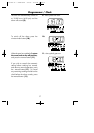
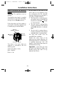
3. Use a 900mm - 1125mm length of
flexible connector. The flexible
connector shall be fitted such that
it cannot come into contact with a
moveable part of the housing unit
(eg; drawer) and does not pass
through any space susceptible of
becoming congested. Make sure
that the flexible connector does not
block the cooling fan inlet.
4. Flexible connections should be to
BS669. Parts of the appliance
likely to come into contact with a
flexible connector have a
temperature rise less than 70°C.
5. Parts of the cooker likely to come
into contact with the flexible hose
have a temperature rise less than
70˚C.
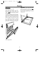
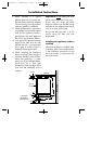
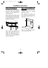
6. Rigid connections must be accessible
to disconnect for servicing. Cut a
150mm square hole in the right
hand rear corner of the support
shelf for the supply pipe.
7. Make sure all connections
are gas sound.
24
Rear
Wall
60 mm
60
mm
60 mm
square
Installation Instructions
08 27250 00 - Creda SC11 9/5/05 3:32 PM Page 26