


27
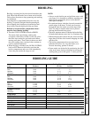
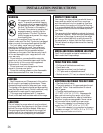
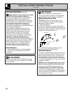
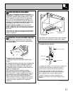
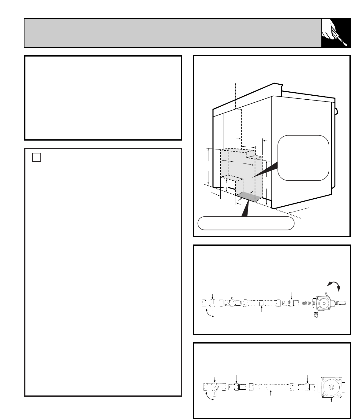
GAS CONNECTION FOR ELECTRIC IGINITION
MODELS
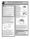
GAS CONNECTION FOR STANDING PILOT MODELS
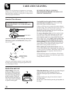
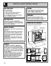
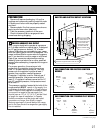
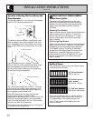
GAS PIPE AND ELECTRIC OUTLET LOCATIONS
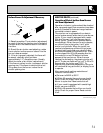
PREPARATION
• Remove all tape and packaging. Lift up the
cooktop and remove any packing material under
it. Make sure the burners are properly seated
and level.
• Remove plastic film that covers some chrome
parts (around oven door, side trim).
• Take the accessory pack out of the oven.
• Check to be sure that no range parts have
come loose during shipping.
PROVIDE ADEQUATE GAS SUPPLY
Your range is designed to operate at a pressure
of 4² of water column on natural gas or, if designed
for LP gas (propane or butane), 10² of water
column. Make sure you are supplying your range
with the type of gas for which it is designed. This
range is convertible for use on natural or propane
gas, if you decide to use this range on a different
type of gas, conversion adjustments must be
made by a service technician or other qualified
person before attempting to operate the range on
that gas.
For proper operation, the maximum inlet
pressure to the regulator should be no more
than 14² of water column pressure. The inlet
pressure to the regulator must be at least 1²
greater than regulator manifold pressure.
Examples: If regulator is set for Natural gas 4²
manifold pressure, inlet pressure must be at
least 5²; if regulator has been converted for LP
gas 10² manifold pressure, inlet pressure must
be at least 11.²
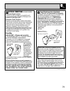
The pressure regulator located at the inlet of the
range manifold
MUST remain in the supply line
regardless of whether natural or LP gas is being
used. A flexible metal appliance connector used
to connect the range to the gas supply line
should have an I.D. of 1/2² or 3/4² and be 5 feet
in length for ease of installation. In Canada,
flexible connectors must be single wall metal
connectors no longer than 6 feet in length.
Seal any openings in the wall behind the range
and in the floor under the range after gas supply
line is installed.
1
Manual
shut-off
valve
Manual
shut-off
valve
Flare
union
Flare
union
Flare
union
Flexible
appliance
conduit
Service shut-
off valve
ON
ON
OFF
OFF
OFF
Flare
union
Pressure
regulator
Pressure
regulator
Flexible
appliance
conduit
(continued next page)
22²
19²
23²
7²
2²
10
1
/
2
²
11
1
/
2
²
7²
C
L
Recommended area
for 120V outlet on
rear of wall and area
for thru the wall
connection of pipe
stub and shut-off
valve is shaded area.
Recommended area for thru the floor
connection of pipe stub and shut-off valve
Centerline
of range
Wall edge
ON