


34
INSTALLATION INSTRUCTIONS
(continued)
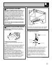
4. Level range if
necessary by
adjusting 4 leg
levelers with wrench.
A minimum clearance
of 1/8² is required
between the bottom of
the range and the rear
leg levelers to allow
room for the Anti-Tip
device.
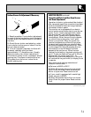
Install the oven
shelves in the oven and
position the range
where it will be
installed. Check for
levelness by placing a
spirit level or a cup,
partially filled with
water, on one of the
oven shelves. If using a
spirit level, take two readings—with the level
placed diagonally first in one direction and
then the other. Adjust the leveling legs until
the range is level.
5. Slide range into place making sure rear legs
are trapped by ends of the 2-piece Anti-Tip
device. Range may need to be shifted slightly to
one side as it is being pushed back to allow rear
legs to align with the device. Open the broiler
compartment to inspect the device. You may also
grasp the top rear edge of the range and
carefully attempt to tilt it forward to make sure
range is properly anchored.
WHEN ALL HOOKUPS ARE COMPLETED:
MAKE SURE ALL CONTROLS ARE LEFT IN THE OFF
POSITION.
MAKE SURE THE FLOW OF COMBUSTION AND
VENTILATION AIR TO THE RANGE IS UNOBSTRUCTED.
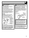
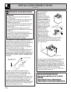
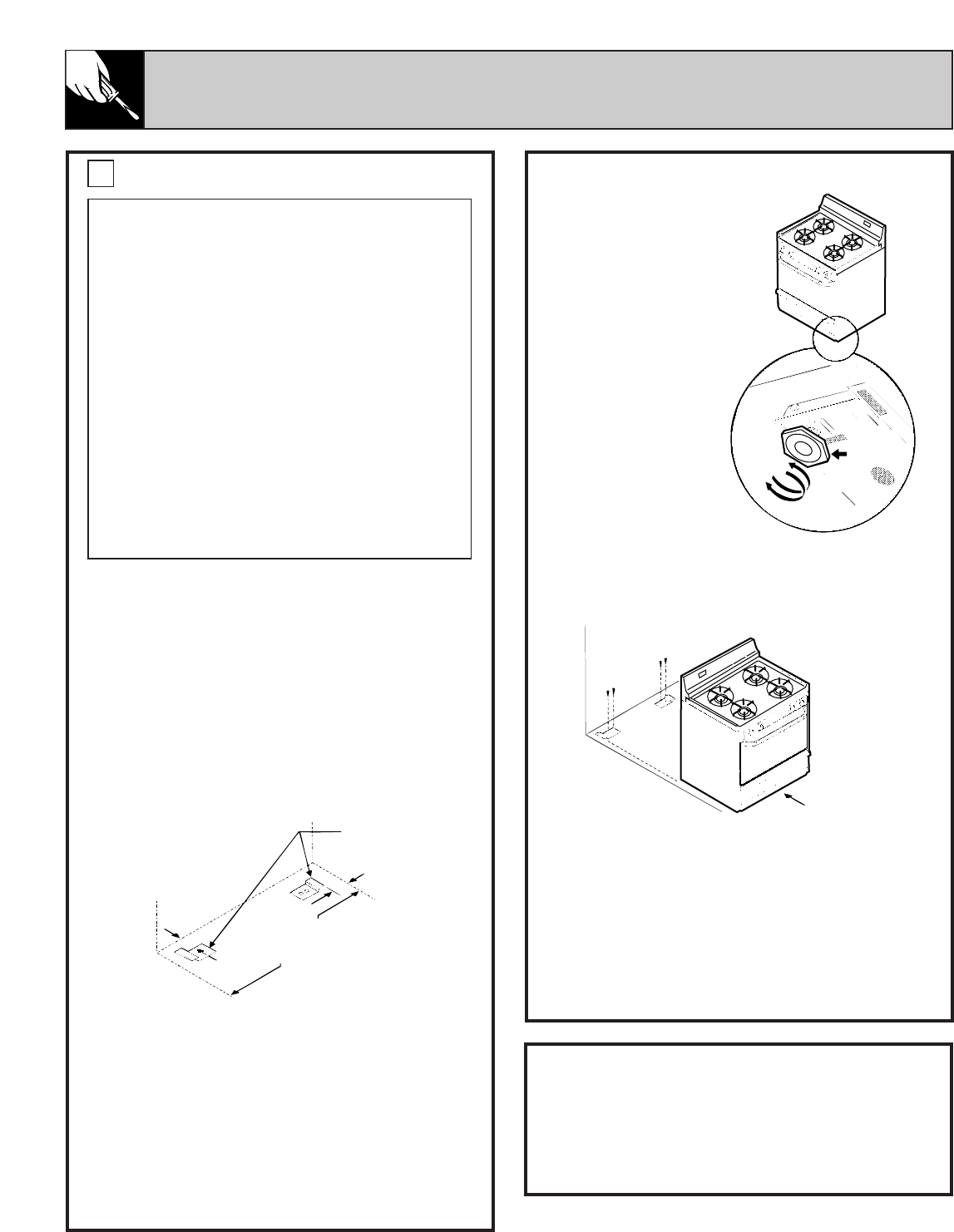
INSTALLING THE 2-PIECE ANTI-TIP DEVICE
The 2-piece Anti-Tip device attaches to the floor
at the back of the range to hold both rear leg
levelers. When fastening to the floor, be sure that
screws do not penetrate electrical wiring or
plumbing. The screws provided will work in
either wood or concrete. The Anti-Tip device is
attached to the back of the range.
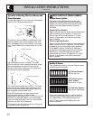
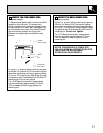
1. Unfold paper template and place it flat on the
floor with the back and side edges positioned
exactly where the back and sides of range will be
located when installed. (Use the diagram below
for the Anti-Tip device location if template is not
available.)
2. Mark on the floor the location of the 4
mounting holes shown on the template. For
easier installation, 3/16² diameter pilot holes
1/2² deep can be drilled into the floor.
3. Remove template and place the 2-piece device
on floor with turned up flange to the front. Line
up holes in brackets with marks on floor and
attach with 4 screws provided. The 2-piece
device must be secured to solid floor. If attaching
to concrete floor, first drill 3/16² diameter pilot
holes using a masonry drill bit.
WARNING:
• Range must be secured with an approved
Anti-Tip device.
• Unless properly installed, the range could be
tipped by you or a child standing, sitting or
leaning on an open door.
• After installing the Anti-Tip device, verify that
it is in place by carefully attempting to tilt the
range forward.
• This range has been designed to meet all
recognized industry tip standards for all normal
conditions.
• The use of this device does not preclude
tipping of the range when not properly installed.
• If the range is ever moved to a different
location, the Anti-Tip device must also be
moved and installed with the range.
9
Back edge of range
wall or rear wall
Anti-Tip device
Range side
panel location
Slide back
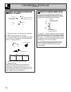
2
7
Ú
8
²
2
1
Ú
4
²
Bottom of range
Leveling
leg
Raise
Lower