


©2007 HUSSMANN CORPORATION • BRIDGETON, MO 63044-2483 U.S.A.
U.S. & CANADA 1-800-504-4828 • WWW.CHILLCHAMBER.HUSSMANN.COM
3
P/N 31033596_B
01 June 2007
™
MAXI-140
Optional Leg Kit
To maintain NSF standards of cleanability
when sealing cannot be done, Hussmann offers
optional leg kits that raises the MAXI-140
four or six inches. Directions are included with
the optional leg kit.
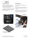
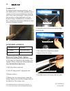
LEVEL
Chill Chambers must be level front-to-back
and side-to-side to operate at peak efficiency.
Shimming may be necessary. Ensure all sides
are firmly supported. Use care when shimming
legs.
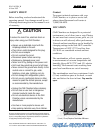
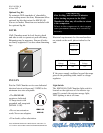
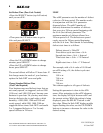
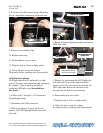
PLUG IN
Put the Chill Chamber on its own dedicated
electrical circuit with ground. 12AWG is the
minimum size wire acceptable.
• The MAXI-140
requires a dedicated
15 Amp circuit with
grounded wall receptacle
(NEMA 5-15P)
• Do not use extension
cords. Never use adapters.
• If in doubt, call an electrician.
Electrical requirements for the merchandiser
are stated on the serial plate attached to the
unit.
If the power supply oscillates beyond the range
given in the preceding table, install a voltage
regulator.
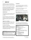
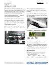
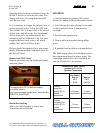
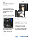
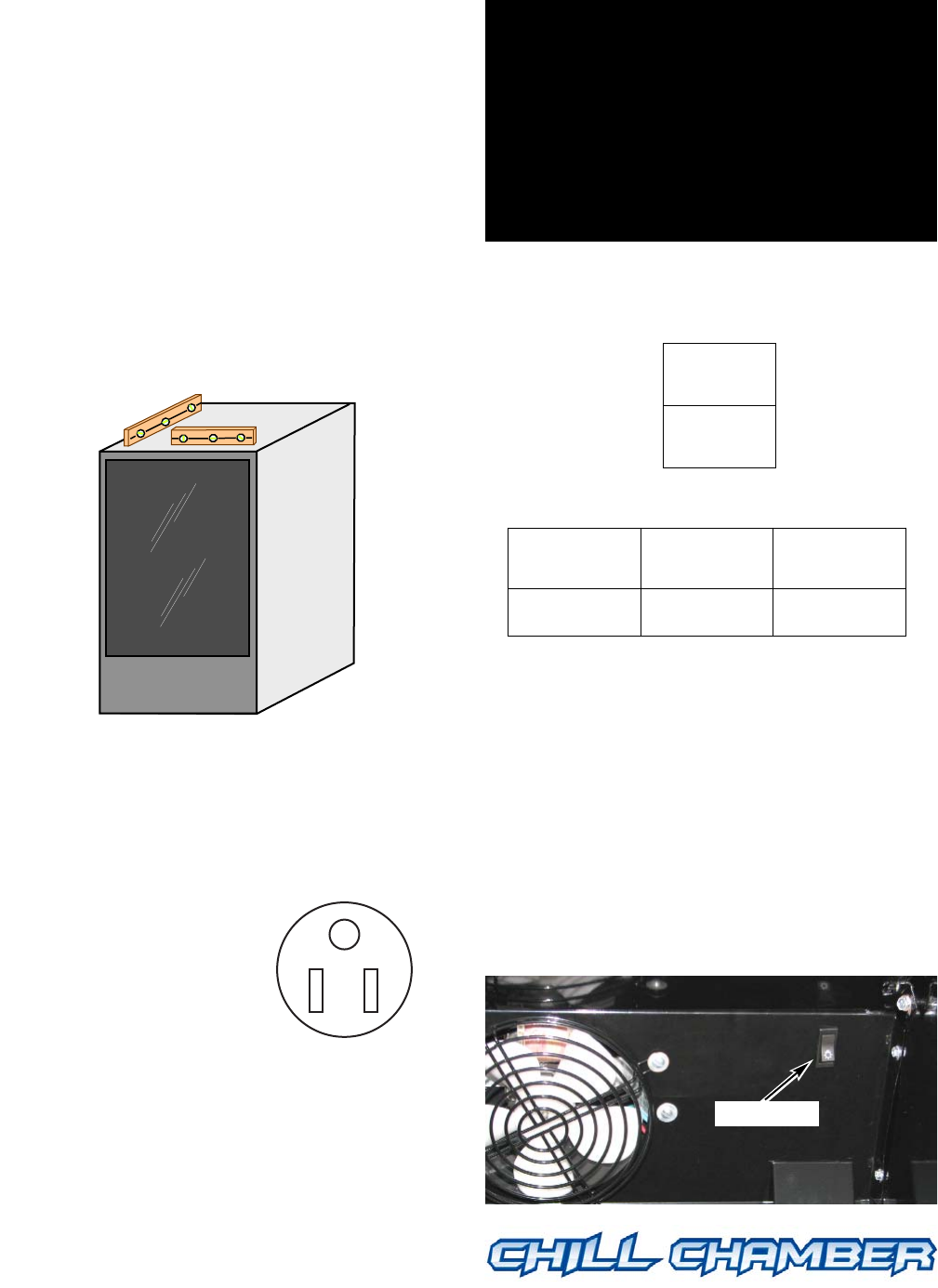
Light Switch
The MAXI-140 Chill Chamber light switch is
located on the right rear of the interior top
panel. It controls the exterior canopy light;
LED lighting is
ON at all times.
™
MAXI-140
™
MAXI-140
™
MAXI-140
™
MAXI-140
™
NEMA 5-15P
MAXI-140
MAXI-140
1000 VA
Nominal
Voltage
Minimum
Voltage
Maximum
Voltage
120 108 132
Light switch
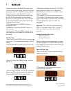
IMPORTANT:
After leveling, wait at least 30 minutes
before turning on power to the Chill
Chamber to allow any oil residue to return
to the compressor.
Oil not in the compressor at start up may
cause permanent damage not covered by
warranty.