


How It Works ICEU060
Page 7
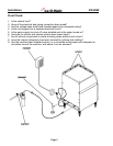
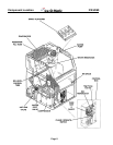
Component Description
Cube Size Control
The Cube size control is located in the front of the control box, behind the front panel. The sensing capillary
tube of the cube size control is routed out of the control box into its bulb holder on the evaporator coil. It is a
reverse acting temperature control with double throw contacts. Turning its knob all the way
counterclockwise also shuts off the icemaker.
Compressor Toggle Switch
The compressor toggle switch is located on the side of the control box. When moved to the ON position, it
makes a circuit to the compressor. When moved to the OFF position, the other components will still
operate.
Water Pump
The water pump operates during the freezing cycle only, pumping water through the spray nozzles into the
inverted spray cups.
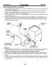
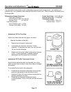
Inlet Water Solenoid Valve
The water solenoid valve, located in the back panel of the unit, is energized only during the harvest or
cleaning cycles. When energized, it allows a metered amount of water to flow into the machine (.21 GPM).
This water flows to the top of the evaporator and then down into the reservoir.
Bin Thermostat Control
The bin thermostat control body is located in front of the control box just beside the cube size control. The
thermostat sensing tube is located in the ice storage bin on the left side wall and will automatically shut the
icemaker off when the bin is full and restart when ice is removed. Factory settings are 36º F cut out and 39º
F cut in. It can be adjusted by turning the adjustment screw visible through the control box cover.
Hot Gas Valve Assembly
The hot gas valve assembly is comprised of two components, the valve body and the coil. These
components are located on the discharge line of the compressor and are activated by the cube size control
(harvest cycle). When the coil of the hot gas valve is energized, it magnetically lifts the plunger in the hot
gas valve body. This allows hot refrigerant gas to by-pass the condenser and go directly to the evaporator.
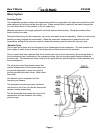
Spray Platform and Chute
The spray system used on this unit is of the stationary type. The water is forced by the water pump into the
platform chamber and sprayed into the inverted cup molds through a set of six spray nozzles.
Fan Motor
The fan motor is electrically connected through the cube size control and runs only during the freeze cycle.
Hermetic Motor Compressor
The compressor is a vapor pump, forcing refrigerant gas throughout the refrigeration system.
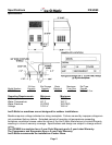
Reference Page 8 for Component Location.