


Ice Frost Operator’s Manual
Publication Number: M620919596OPR - 18 - © 2004-2006, IMI Cornelius Inc.
OFF CONDITION
In this condition, the electronic control is not connected to the power supply. To connect the ECB to the
power supply, the main system switch must be put in the ON position.
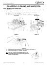
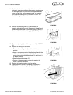
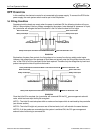
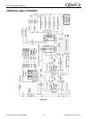
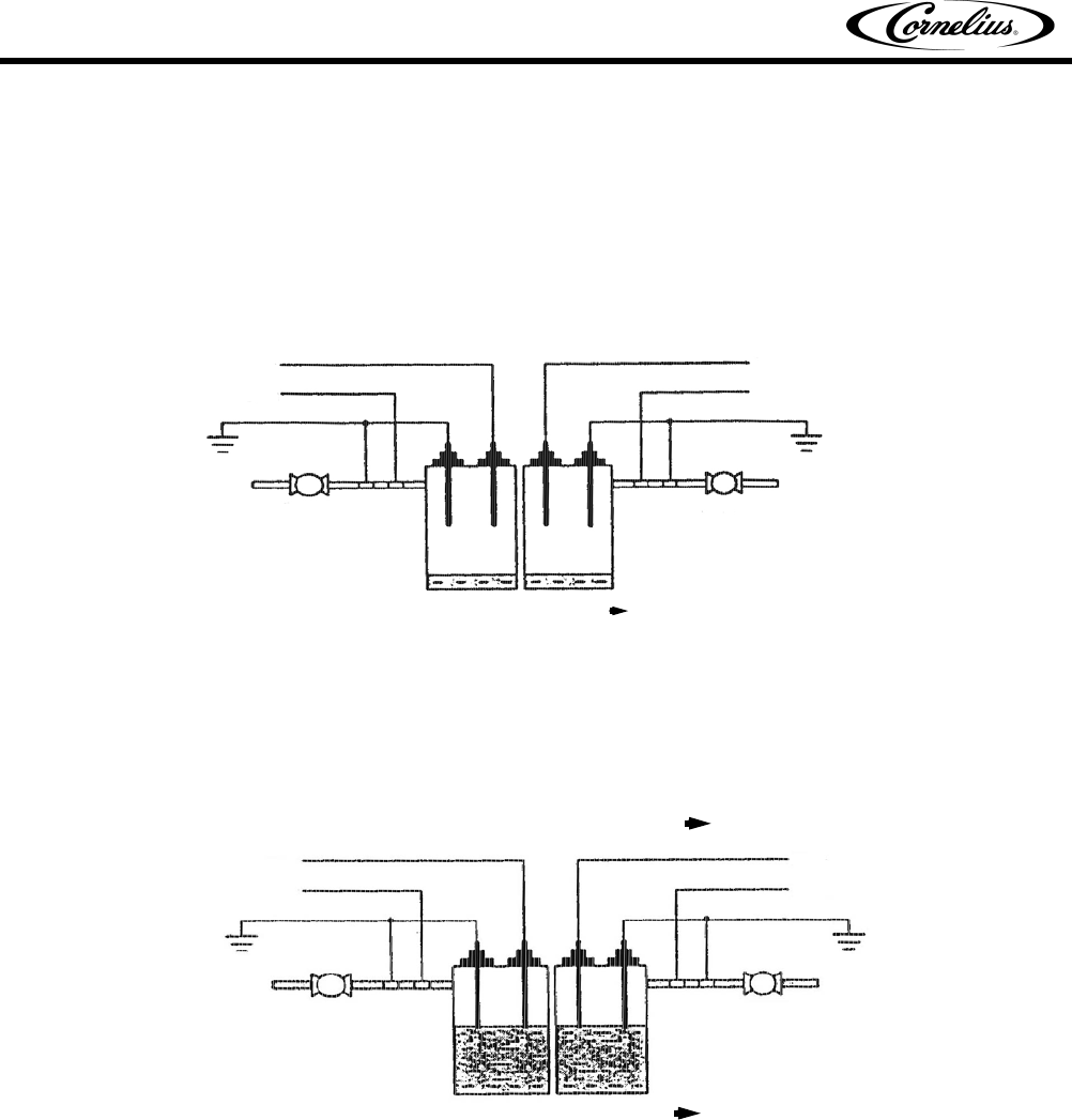
1st Filling Condition
Supposing both the bowls are empty when the power is switched ON, the following situation will occur:
After a 3 second delay if the four probes, managed by the system, have detected no ‘presence’ of liquid,
the (μcontroller will energies the bowl fill solenoid 1 and 2 to allow the bowl to fill to begin.
FIGURE 32
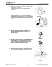
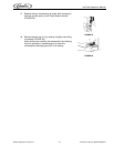
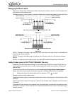
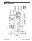
Explanation of system flow controls, the first probes to be ‘covered’ are the two safety probe inputs.
However, this recognition of the passage of liquid does not actually stop the filling phase since the main
‘aim’ of the ECU is to fill the two bowls to the level required. Therefore only the recognition by bowl level
probes interrupts the inlet of liquid into the bowl/s.
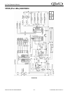
FIGURE 33
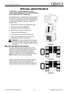
Once the initial fill is complete, the (μcontroller will command ON the CO
2
gas management solenoid
valve, which has been kept forcibly de-energized.
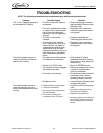
NOTE 1: The initial fill must take place within a maximum time lapse which is monitored by the μcontroller
(see Alarms section).
NOTE 2: The initial fill might only concern one of the two bowls, but it will maintain the same features.
NOTE 3: If all the probes are covered when the system is switched ON, the CO
2
gas management
solenoid valve functioning is command ON.
Bowl Level Probe
Bowl Level Probe
Safety Probe Input
Safety Probe Input
Safety Probe Inputs and Bowl Level Probes Uncovered Bowl Fill Solenoids = ON
Bowl Fill Solenoid
Bowl Fill Solenoid
Bowl Level Probe
Bowl Level Probe
Safety Probe Input
Safety Probe Input
Safety Probe Inputs Covered and Bowl Level Probes Covered Bowl Fill Solenoids = ON
Safety Probe Inputs Covered and Bowl Level Probes Uncovered Bowl Fill Solenoids = ON
Bowl Fill Solenoid
Bowl Fill Solenoid