


Ice Frost Operator’s Manual
© 2004-2006, IMI Cornelius Inc. - 3 - Publication Number: M620919596OPR
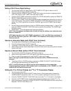
CONNECTION DIAGRAMS
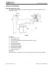
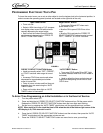
Ice Frost Generic (Pre-mix)
The diagram shows the sequence for the connection between the ICE FROST GENERIC PRE to an
existing pre-mix system.
FIGURE 3
Description:
1. Pre-mix product 1 inlet.
2. Pre-mix product 2 inlet.
4.
Inlet for CO
2
(coming from the pressure reducing valve, 12 psi).
5. CO
2
gas cylinder.
6. Operating pressure gauge.
7.
CO
2
pressure regulator.
8. Gas cylinder pressure gauge.
9. Pre-mix product 1 container.
10. Pre-mix product 2 container.
11. Cooling unit (Optional).
Connection:
Connect the points 1, 2, and 4 on the machine to the existing pre-mix system using quick couplings.