


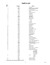

291875
INSTALLATION INSTRUCTIONS
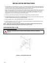
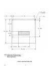
1. The ice dispenser must be sealed to the counter. The template drawings (page 4) indicate openings which
must be cut in the counter. Locate the desired position for the dispenser, then mark the outline dimensions
and cut out locations using the template drawing. Cut openings in the counter.
Apply a continuous bead of NSF International (NSF) approved silastic sealant (DOW 732 or equal) approxi-
mately 1/4” inside of the unit outline dimensions and around all openings. Then position the unit on the
counter within the outline dimensions. All excess sealant must be wiped away immediately. The sink is
shipped loose and is not to be sealed to provide service access.
2. Carefully pull the drain line and power cord through the large opening in the bottom of the unit.
3. Connect the drain tube to an open drain. If additional piping is required, it must be 3/4” IPS (or equal) and
must pitch downward away from the unit for proper drainage.
4. Clean the hopper interior. (See CLEANING INSTRUCTIONS on pages 5 & 5 ).
5. Connect the power cord to a 115 volt, 60 cycle, 3-wire grounded receptacle. All electrical wiring must con-
form to national and local electrical codes.
NOTE: Water pipe connections and fixtures directly connected to a potable water supply shall be
sized, installed and maintained according to federal state, and local laws.
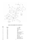
GATE RESTRICTOR PLATE
CAUTION: Disconnect power to dispenser before installing, removing or adjusting
restrictor.
FIGURE 1. GATE RESTRICTOR PLATE