


Countertop Icemaker IMD Series Installation Manual
Publication Number: 638085277INS - 10 - © 2004-2009, IMI Cornelius Inc.
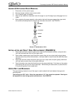
The operating positions of the switch are fixed, no adjustments are necessary. If switch replacement
becomes necessary, simply disconnect cable at connector, remove wires from switch.
NOTE: The thermostatic expansion valve is non-adjustable on all models.
REFRIGERATION SYSTEM ADJUSTMENTS
A complete understanding of the icemaker and hermetic refrigeration system is necessary before any
adjustments are made. The refrigeration technician must use high and low side pressure readings,
water, and air temperatures, plus general conditions of cleanliness to assess the refrigeration system sta-
tus when making any adjustments.
All icemaker products are tested and adjusted at the factory prior to shipment where the ambient temper-
ature ranges from 65
o
F to 90
o
F, depending on the season of the year.
Whenever a new icemaker is initally installed and started-up, it is imperative that the start-up operator
make the following checks and readjustments for local conditions.
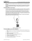
EXPANSION VALVE
You will find a thermal expansion valve on icemakers, which is used to control the amount of refrigerant
flowing through the evaporator. Improperly installed or defective expansion valves may cause low pro-
duction, soft ice, squeaking from evaporator and excessive load inside evaporator.
By using general refrigeration troubleshooting along with the pressure charts, you can easily determine
whether or not the expansion valve is working properly.
ADJUSTMENT AND TROUBLESHOOTING
When troubleshooting the expansion valve, you must:
1. Be sure you have adequate water flowing into the evaporator, a clean and properly ventilated con-
denser, and the system is properly charged and free of any restrictions. Also be sure compressor is
operating properly.
2. Take reservoir water temperature and air temperature from condenser inlet and determine at what
pressure unit should be running. On machines equipped with thermostatic valve there is NO adjust-
ment. If correct pressure cannot be obtained, be sure system has time to stabilize, 10-15 minutes.
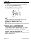
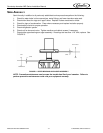
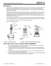
3. Be sure sensing bulb is located at outlet side of evaporator about 3-4 inches away from evaporator
and be sure to insulate well and clamp tightly to tubing. If system pressures are still not adequate,
take a second water and air temperature reading and go over other parts of the system for possible
problems. If proper charge is questionable evacuate and recharge to nameplate and leak check. If
valve still malfunctions replace valve.
Use general refrigeration system practices when replacing and recharging unit. After new valve is in
place, go through previous monitored adjustments and troubleshooting to be sure valve is functioning
properly.
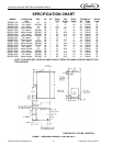
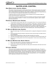
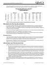
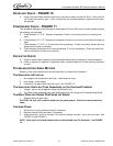
Temperature/Pressure Charts*
10 lbs. Discharge Pressure
Water Temperature
IMD300-15 IMD300-30 IMD600-30 & IMD600-90
Air Temperature
40
o
65
o
90
o
40
o
65
o
90
o
40
o
65
o
90
o
50
o
80 85 90 162 166 168 174 177 180
60
o
92 97 102 188 192 194 202 205 208
70
o
114 120 124 214 218 220 230 233 236
80
o
124 120 147 245 249 251 265 269 272
90
o
161 167 171 275 279 281 300 304 307
100
o
187 193 195 309 313 315 328 334 340