


Countertop Icemaker IMD Series Installation Manual
© 2004-2009, IMI Cornelius Inc. - 15 - Publication Number: 638085277INS
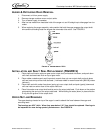
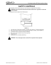
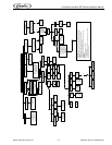
OVERLOAD CHECK - FIGURE 10
4. Using a volt-ohm meter check the continuity across the overload, contacts #1 & #3. If none, wait for
unit to cool down and try again. If still no continuity, the overload protector is defective and should
be replaced.
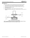
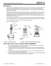
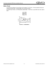
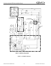
COMPRESSOR CHECK - FIGURE 11
The resistance readings on the windings will be between 0.25 and 10.00 ohms, a meter capable of these
low readings must be used.
5. Check between “C” & “R”. Replace compressor if there is no continuity as the run windings are
open.
6. Check between “C” & “S”. Replace the compressor if there is no continuity as the start windings are
open.
7. Check between “C” & “R”, or “S” and shell of the compressor. If there is continuity replace the com-
pressor as the motor is grounded.
8. Check between screw terminal on the overload and “C” on the compressor. Check and repair the
lead or connections if there is no continuity.
CAPACITOR CHECK
9. Check or replace start capacitor, disconnect bleed resistor before checking for shorted capacitor.
10. Check or replace run capacitor (if supplied) check or shorted capacitor or either terminal grounded
to case.
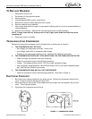
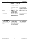
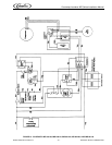
TROUBLESHOOTING GEAR MOTORS
Basically, Gear motor problems can be narrowed down to three areas of checkout.
The Gearmotor will not run
1. No voltage to the transmission terminals - check external circuit.
2. Low voltage - check supply.
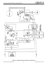
3. Problems in the gear motor electrical circuit. See FIGURE 12.
The Gearmotor Starts but Trips Repeatedly on the Overload Protector
1. Voltage - high or low voltage can cause the overload to trip.
2. High Gear motor amperage draw, see Specification Chart for ratings and Troubleshooting Guide.
The Motor Runs but Output Shaft does not Rotate
1. Replace defective gear motor.
CAUTION: Be sure unit is disconnected from the power source. Disconnect the transmission
cable.
Overload Check
1. Allow motor to cool and reset overload if necessary.
2. Remove motor end bell and stator, if necessary.
3. Check terminals 1 and 3 on overload. No continuity replace overload. Use a volt-ohm meter. See
FIGURE 10 and FIGURE 11.
NOTE: Gear motor and related components can be checked from Pin Connector. See FIGURE
12.